


3-40
Cisco 3600 Series Routers Hardware Installation Guide
OL-2056-05
Chapter 3 Installing the Router
Connecting WAN, LAN, and Voice Cables
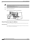
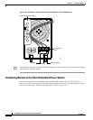
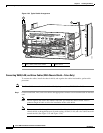
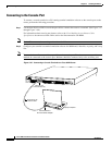
Figure 3-53 Typical Cable Arrangement
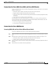
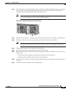
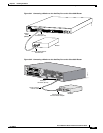
Connecting WAN, LAN, and Voice Cables (With Chassis Shield—Telco Only)
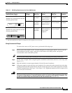
To connect the cables, install the chassis shield, and organize the cables into bundles, perform this
procedure:
Note The Cisco 3660 router telco chassis is identified by its part number, CISCO3662-xC-CO.
Step 1 Connect each WAN, LAN, and voice cable to the appropriate connector on a network module or interface
card.
Note Do not organize the cables into bundles until after you install the chassis shield. Leave a
generous length of cable to allow for installation of the cable shield.
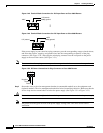
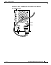
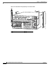
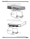
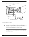
Note You can route cables through the cutout at the left of the chassis, through the openings in the
chassis shield, or through both areas. In each routing, all WAN, LAN, and voice cables must exit
toward the left. (See Figure 3-55 and Figure 3-56.)
1 LAN, WAN, and voice cables 2 Power wires
82351
V
C
C
O
K
S
Y
S
T
E
M
F
D
X
L
I
N
K
1
0
0
M
b
p
s
F
D
X
1
0
L
I
N
K
1
0
0
M
b
p
s
ETH 0
ETH 3
E
TH
ERN
ET
4E
ETH 2
ETH 1
1
23
ACT
LINK
0
C
N
/L
P
R
X
C
S
E
R
IA
L
3
S
E
R
IA
L
2
S
E
R
IA
L
1
S
E
R
IA
L
0
R
X
DT
X
C
T
X
D
C
N
/L
P
R
X
C
R
X
D
TX
C
T
X
D
C
N
/LP
R
X
C
R
X
D
T
X
C
T
X
D
C
N
/L
P
R
X
C
R
X
D
T
X
CTX
D
E
N
S
E
R
IA
L
4
T
VO
IC
E
2V
V
0
V1
EN
H
IG
H
S
P
E
E
D
S
E
R
IA
L
1
H
S
S
I
H
TD
TC
RD
RC
LB/CN
SEE MANUAL BEFO
RE INSTALLATIO
N
V
IC
FXS
IN USE
IN USE
1
0
1
2