


1-2
Cisco ASR 901 Series Aggregation Services Router Hardware Installation Guide
OL-23778-01
Chapter 1 Introduction
Hardware Description
• Two management ports: RS-232 serial console and 10/100 Base-T Ethernet ports
• One BITS clock port (RJ45) and 1 ToD port (RJ45)
• Two miniature coaxial connectors for 10Mhz and 1PPS timing (input or output). You can use these
interfaces with an external GPS device to send or receive clocking from the router.
• Two LEDs for each T1/E1 port
–
C—indicates out of service or not configured, carrier condition, and loop condition
–
AL—no alarm, or alarm condition
• Two LEDs for each Ethernet port
–
L—indicates activity, lack of activity, or no link
–
S—indicates speed (100 or 1000) or off
• One System LED:
–
Solid Green—System Healthy (normal operation)
–
Solid RED—System Faulty
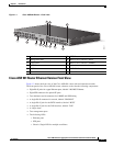
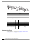
Cisco ASR 901 Router Front View
Figure 1-1 shows the front view of the Cisco ASR 901 router with each interface module.
The front panel of the Cisco ASR 901 router has the following components:
• 16 T1/E1 ports, labelled T1/E1 (positions 1, 2, 3, 4, 5, 6, 7, 8, 9, 10, 11, 12, 13, 14,15 and 16)
• Eight RJ-45 jacks for copper Ethernet ports, labeled “100/1000” Ethernet.
• Eight SFP connectors for optical GE ports
• Two miniature coaxial connectors for 10MHZ and 1PPS timing
• A single RJ-45 connector for console, labeled “CONSOLE”
• A single RJ-45 jack for the BITS interface, labeled “BITS”
• A single RJ-45 jack for the ToD interface, labeled “ToD”
• A single alarm
• Two management ports
• The following LEDs
–
T1/E1 ports
–
Ethernet ports
–
SFP ports
–
Chassis: Single LED for multiple conditions