


B-4
Cisco ASR 901 Series Aggregation Services Router Hardware Installation Guide
OL-23778-01
Appendix B Cable Specifications
Console Port Signals and Pinouts
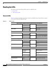
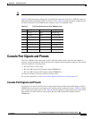
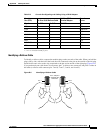
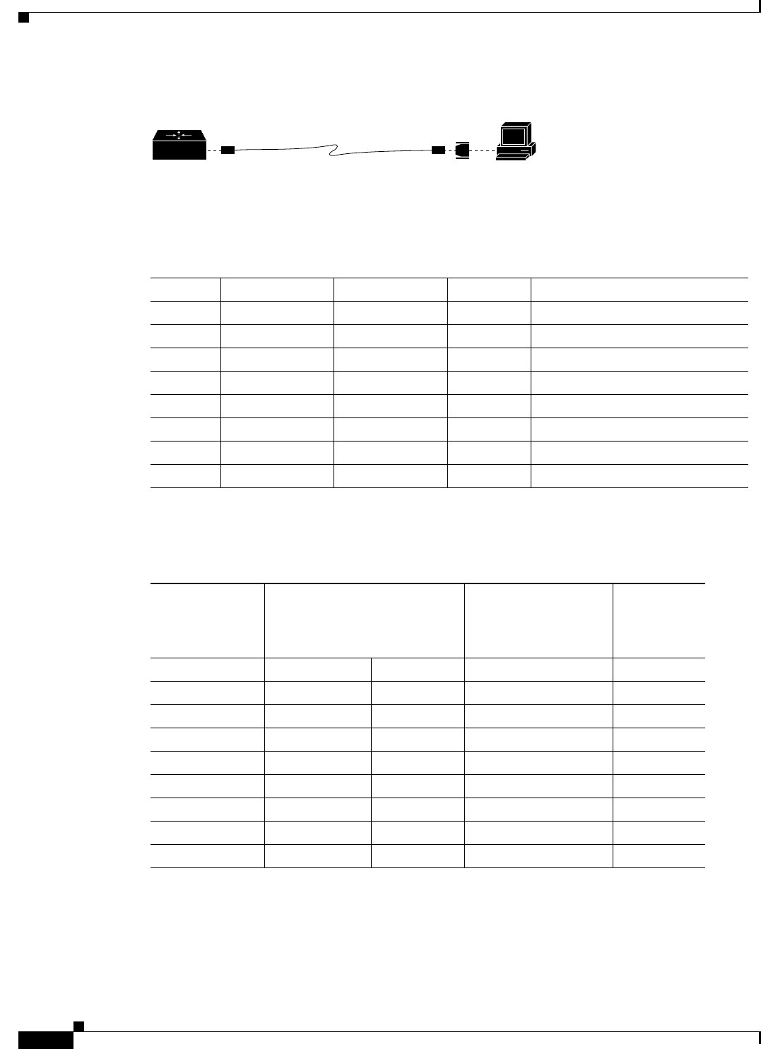
Figure B-4 Connecting the Console Port to a PC
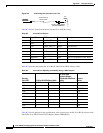
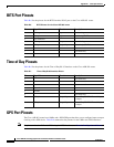
Table B-3 lists the Console port pinouts for the Cisco ASR 901 router.
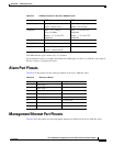
Table B-4 describes the pinouts RJ-45-to-RJ-45 and RJ-45-to-DB-9 rollover cables.
Table B-5 lists the pinouts for the asynchronous serial console port, the RJ-45-to-RJ-45 rollover cable,
and the RJ-45-to-DB-25 female DTE adapter (labeled TERMINAL).
PC
H7226
RJ-45-to-RJ-45
rollover cable
RJ-45-to-DB-9 adapter
(labeled TERMINAL)
Router
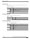
Table B-3 Console Port Pinouts
Pin Signal Name HP Pins Direction Description
1 RTS UART_RTS1 Output Request to send
2 DTR NC
3 TXD UART_SOUT1 Output Transmit data
4 RI GND Ring indicator
5 GND GND
6 RXD UART_SIN1 Input Receive data
7 DSR/DCD NC Input Data set ready/Data Carrier detect
8 CTS UART_CTS1 Input Clear to send
Table B-4 Console Port Signaling and Cabling Using a DB-9 Adapter
Console
Port (DTE) RJ-45-to-RJ-45 Rollover Cable
RJ-45-to-DB-9
Terminal Adapter
(Connected to Rollover
Cable)
Console
Device
Signal RJ-45 Pin RJ-45 Pin DB-9 Pin Signal
RTS 1
1
1. Pin 1 is connected internally to pin 8.
88 CTS
DTR 2 7 6 DSR/DCD
TxD 3 6 2 RxD
GND/RI 4 5 5 GND
GND 5 4 5 GND/RI
RxD 6 3 3 TxD
DSR/DCD 7 2 4 DTR
CTS 8
1
1 7 RTS