


1-6
Cisco ASR 901 Series Aggregation Services Router Hardware Installation Guide
OL-23778-01
Chapter 1 Introduction
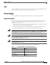
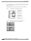
Power Supply
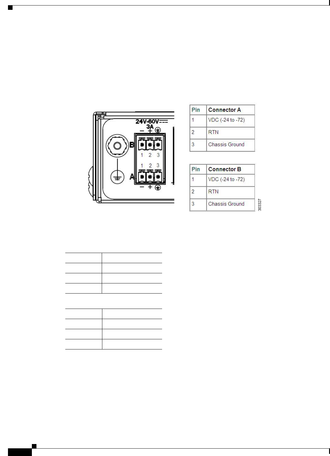
The Cisco ASR 901 router uses two 3 pin connectors (part number 27-2030-01) for input to the power
supply. The terminal block is part of the accessory kit (part number 53-3085-01/53-3295-0), which ships
with the Cisco
ASR 901 router.
The ground wire connects to a 2-hole plug, which connects to the corresponding mounting point.
With the connector installed in the chassis, the pins are numbered as 1,2, and 3, respectively.
Figure 1-4 Cisco ASR 901 Router—Power Supply Connector Pinouts
Table 1-2 lists the pinout configurations for the connector, based on the power source.
You can use connector A or B or both.
Table 1-2 Power Supply Connector Pinouts (-24/-72 VDC Application)
Pin Connector A
1 VDC (-24 to -72)
2 RTN
3 Chassis Ground
Pin Connector B
1 VDC (-24 to -72)
2 RTN
3 Chassis Ground