


1-3
Cisco ASR 901 Series Aggregation Services Router Hardware Installation Guide
OL-23778-01
Chapter 1 Introduction
Hardware Description
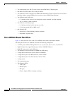
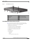
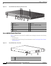
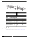
Figure 1-1 Cisco ASR 901 Router—Front View
Cisco ASR 901 Router Ethernet Version Front View
Figure 1-2 shows the front view of the Cisco ASR 901 router with each interface module.
The front panel of the Cisco ASR 901 router, ethernet version has the following components:
• Eight RJ-45 jacks for copper Ethernet ports, labeled “100/1000” Ethernet.
• Eight SFP connectors for optical GE ports
• Two miniature coaxial connectors for 10MHZ and 1PPS timing
• A single RJ-45 connector for console, labeled “CONSOLE”
• A single RJ-45 jack for the BITS interface, labeled “BITS”
• A single RJ-45 jack for the ToD interface, labeled “ToD”
• A single alarm
• Two management ports
• The following LEDs
–
Ethernet ports
–
SFP ports
–
Chassis: Single LED for multiple conditions
282341
SYSTEM
CONSOLE
BITS
1 PPS
MGMNT
TOD
10 MHz
T1/E1
ALARM
B
A
+
-
+
-
24V - 60V
3A
COMBO
SFP
NG-MRW
GE
3
12
2
1
11
6
7
8
10
9
5
4
1 ToD Port 7 BITS Port
2 Management Port 8 MINI-Coax Connector (1PPS)
3 Power LED 9 MINI-Coax Connector (10MHZ)
4 8 SFP Ports 10 Alarm
5 8 GE Ports 11 16 T1/E1 Ports
6 Console Port 12 Power Connector