


B-3
Cisco ASR 901 Series Aggregation Services Router Hardware Installation Guide
OL-23778-01
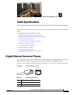
Appendix B Cable Specifications
Console Port Signals and Pinouts
Note We recommend using a shielded cable for RJ-48C connectors.
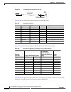
Table B-2 shows the pinout configuration for the RJ-48C connectors on the Cisco ASR 901 router for
both the shielded and unsaddled cables for either T1 or E1. Table B-2 shows the pinout configuration for
the RJ-45 connectors on the TDM interface module on the Cisco ASR 901 router.
Console Port Signals and Pinouts
The Cisco ASR 901 router ships with a console cable kit, which contains the cable and adapters to
connect a console terminal (an ASCII terminal or PC running terminal emulation software). The console
cable kit includes the following items:
• RJ-45-to-RJ-45 rollover cable
• RJ-45-to-DB-9 female DTE adapter (labeled TERMINAL)
• RJ-45-to-DB-25 female DTE adapter (labeled TERMINAL)
To connect a modem, you need to order an auxiliary cable.
For console connections, see the “Console Port Signals and Pinouts” section on page B-3.
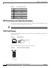
Console Port Signals and Pinouts
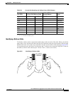
Use the thin, flat, RJ-45-to-RJ-45 rollover cable and the RJ-45-to-DB-9 female DTE adapter (labeled
TERMINAL) to connect the console port to a PC running terminal emulation software.
Figure B-4 shows
how to connect the console port to a PC. Table B-4 lists the pinouts for the asynchronous serial console
port, the RJ-45-to-RJ-45 rollover cable, and the RJ-45-to-DB-9 female DTE adapter (labeled
TERMINAL).
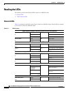
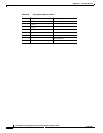
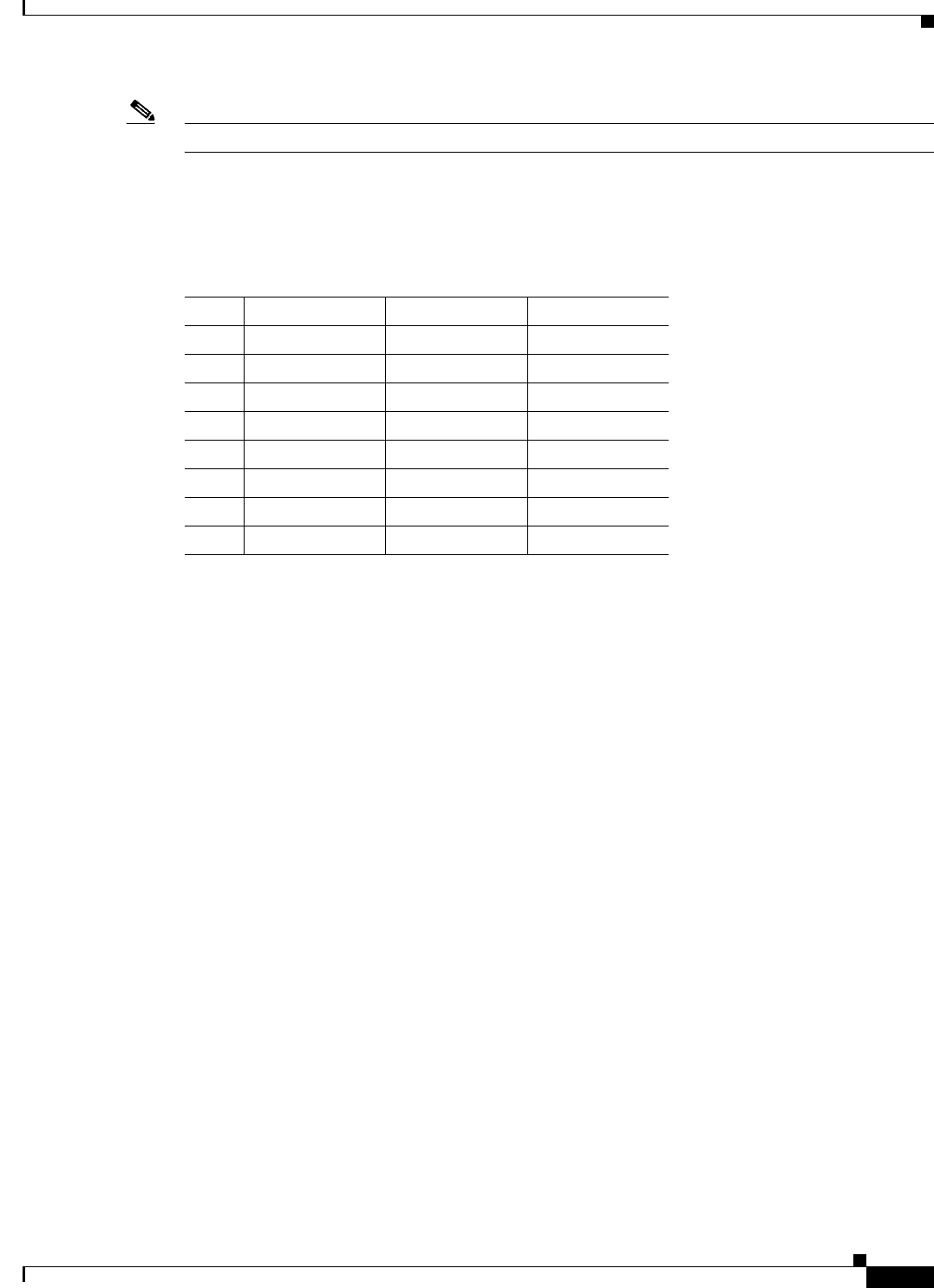
Table B-2 T1/E1 Port Pinout for the Cisco ASR 901 router
Pin Signal Name Direction Description
1 RX Tip Input Receive Tip
2 RX Ring Input Receive Ring
3 Not used
4 TX Tip Output Transmit Tip
5 TX Ring Output Transmit Ring
6 Not used
7 Not used
8 Not used