


3-14
Cisco ASR 901 Series Aggregation Services Router Hardware Installation Guide
OL-23778-01
Chapter 3 Installing the Cisco ASR 901 Mobile Wireless Router
Connecting Cables
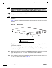
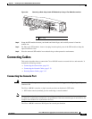
Connecting SFP Cables
Complete these steps to connect the cable to a router SFP port.
Step 1 Confirm that the router is powered off.
Step 2 Insert the SFP module patch cable into the slot until you feel the connector on the cable snap into place
in the rear of the slot.
Step 3 Connect the other end to the patch or demarcation panel at your site.
Step 4 Turn on power to the router (see “Powering On the Router” section on page 3-15 for more details).
For more information about SFP connectors, see “SFP Port Pinouts and Cable Specifications” section
on page B-2.
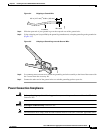
Connecting Cables to the BITS Interface
Complete these steps to connect the cable to the router BITS port:
Step 1 Confirm that the router is powered off.
Step 2 Connect one end of the cable to the BITS port using a T1/E1 cable.
Step 3 Connect the other end to the SETS unit.
Step 4 Turn on power to the router (see “Powering On the Router” section on page 3-15 for more details).
For more information about T1/E1 connectors including pinouts, see “BITS Port Pinouts” section on
page B-6.
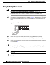
Connecting GPS Cables
The following sections describe how to connect cables from the Cisco ASR 901 router to a GPS unit for
input or output timing or frequency.
• Connecting Cables to the 10Mhz or 1PPS Interface
• Connecting Cables to the ToD Interface
Connecting Cables to the 10Mhz or 1PPS Interface
Complete these steps to connect cables to the 10Mhz or 1PPS interface:
Step 1 Confirm that the router is powered off.
Step 2 Connect one end of a mini-coax cable to the GPS unit.
Step 3 Connect the other end of the mini-coax cable to the 10Mhz or 1PPS port on the Cisco ASR 901 router.
For instructions on how to configure clocking, see the Cisco ASR 901 Mobile Wireless Router Software
Configuration Guide.