


3-8
Cisco ASR 901 Series Aggregation Services Router Hardware Installation Guide
OL-23778-01
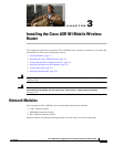
Chapter 3 Installing the Cisco ASR 901 Mobile Wireless Router
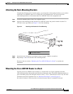
Mounting the Cisco ASR 901 Router
Wiring the DC-Input Power Source
Warning
This product relies on the building’s installation for short-circuit (overcurrent) protection. Ensure that
the protective device is rated not greater than 10 A minimum, 60 VDC.
Statement 1005
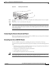
Complete the following steps to connect the DC power supply to the Cisco ASR 901 router:
Step 1 Switch off the DC power source at the circuit breaker, and place the circuit breaker in the Off position.
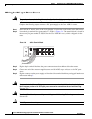
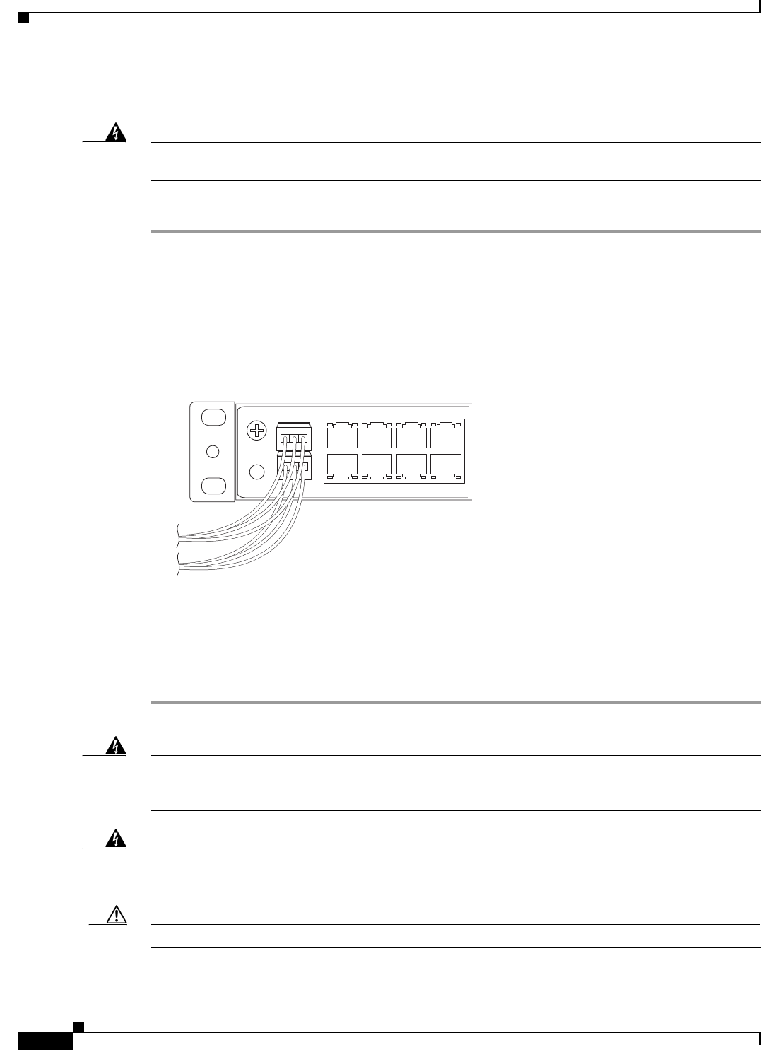
Step 2 Locate the 6-pin terminal block (part number 27-2030-01) (Figure 3-6). The terminal block is located in
the accessory kit (part number 53-3085-01 for the Cisco ASR 901 router), which is shipped with the
router.
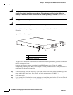
Figure 3-6 6-Pin Terminal Block
Step 3 Plug the 6-pin terminal block into the power connector located on the front side of the router.
Step 4 Connect one end of the customer-supplied power cord (16-AWG copper wire) to the site DC power
source.
Step 5 Plug the connector on the power supply cord into the 6-pin terminal block that you plugged into the rear
of the router in Step 3.
Warning
An exposed wire lead from a DC-input power source can conduct harmful levels of electricity. Be sure
that no exposed portion of the DC-input power source wire extends from the terminal block plug.
Statement 122
Warning
When installing this unit, secure all power cabling to avoid disturbing field-wiring connections.
Statement 38
Caution DO NOT power on the unit yet.
282346