


3-4
Cisco ASR 901 Series Aggregation Services Router Hardware Installation Guide
OL-23778-01
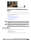
Chapter 3 Installing the Cisco ASR 901 Mobile Wireless Router
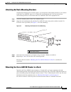
Mounting the Cisco ASR 901 Router
To secure the Cisco ASR 901 router to the equipment rack, you must use the two mounting screws
(provided) for each side or follow your local practices for installing the router into your equipment rack.
Ensure that the rack-mount brackets are securely fastened. For more information, see the
“Attaching the
Rack-Mounting Brackets” section on page 3-3.
To mount the Cisco ASR 901 router into the equipment rack, perform the following procedure.
Caution To prevent injury, review the “Safety Guidelines” section on page 2-1 and the “Rack-Mounting
Configuration Guidelines” section on page 3-2 before installing the Cisco ASR 901 router in the
equipment rack.
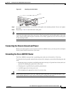
Step 1 Locate the equipment rack position where you plan to install the router.
Step 2 Verify that there are no obstructions and ensure that the equipment rack is stabilized.
Step 3 Position the router in the equipment rack lining up the bracket holes on the router with the holes on the
rack and secure with four #6-32 x 0.25-inch mounting screws (two on each side).
Note The vertical spacing for EIA equipment racks is 1.75 inches (4.44 cm), with mounting holes
spaced 1.5 inches (3.81 cm) apart.
Step 4 Tighten the screws using a 1/4-inch flat-blade screwdriver (each side).
Attaching the Cable Guides
Complete the following steps to attach the two cable guides to the front of the mounting brackets. This
procedure is optional.
Note The cable guides are useful only if your router is front-mounted. Do not attach the cable guides if your
router is center-mounted or recess-mounted.
Use the cable guides to dress the cables that attach to the front of the Cisco ASR 901 router. The cable
guides allow you to gather the cables and direct them to the left and right sides of the router. This helps
to keep the cables from obscuring the fronts of lower routers in the same rack.
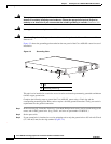
Step 1 In the accessory kit, locate the two cable guides (part number 700-01663-01) and two M4.0x20mm
Phillips screws used to attach the cable guides (part number 48-0654-01).
Step 2 Position the cable guide over the threaded hole in the front flange of either the left or right mounting
bracket. The threaded hole is located midway between the two slotted holes used to mount the unit to
the rack.