


A-5
Cisco ASR 901 Series Aggregation Services Router Hardware Installation Guide
OL-23778-01
Appendix A Troubleshooting
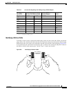
Reading the LEDs
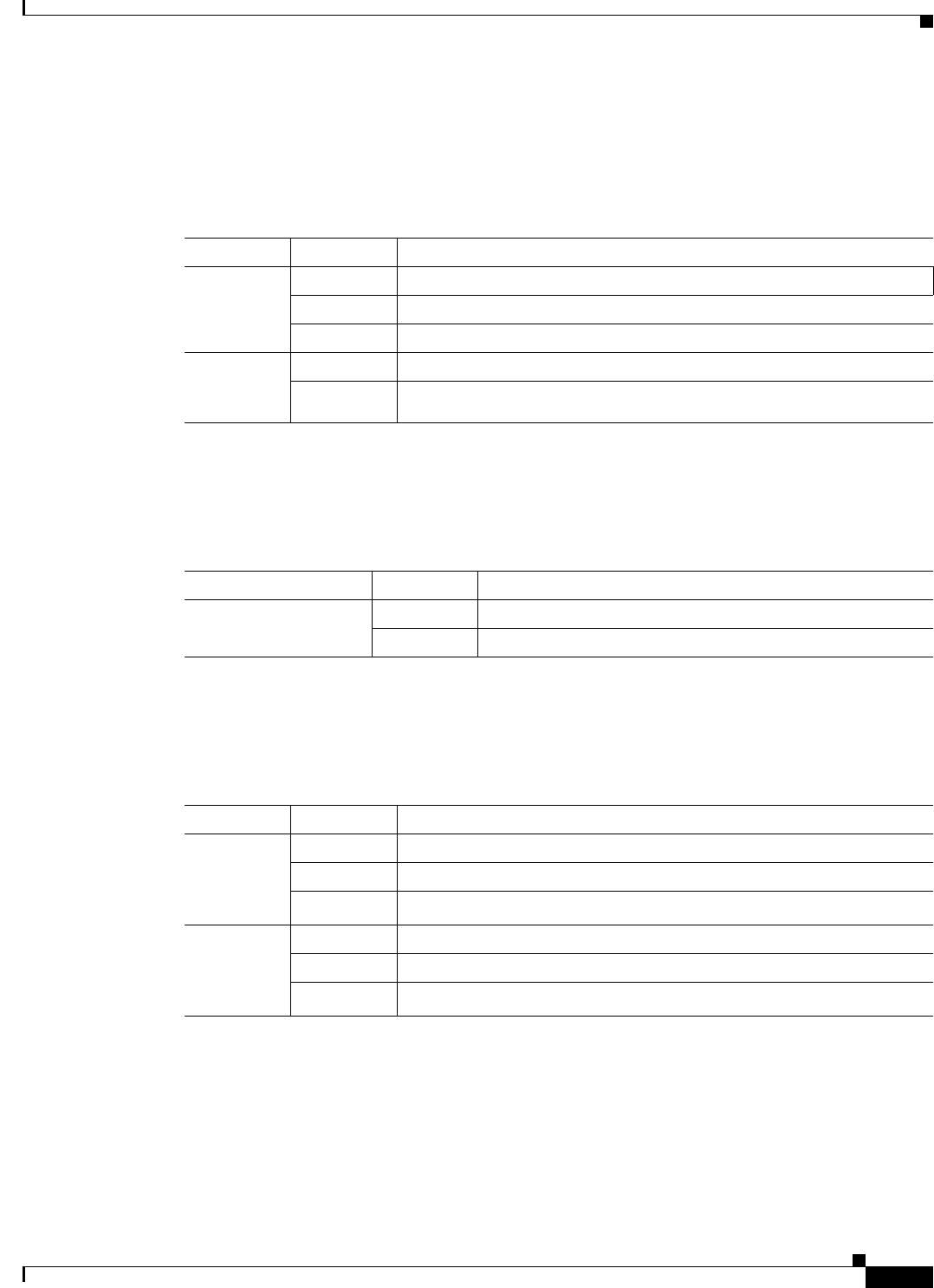
T1/E1 Interface LEDs
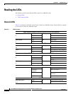
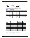
Table A-5 summarizes the LEDs on the T1/E1 interface (available only for A901-12C-FT-D and
A901-4C-FT-D).
SFP Ethernet Interface LEDs
Table A-6 gives information about the LEDs on the SFP interface.
RJ-45 Ethernet Interface LEDs
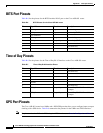
Table A-7 summarizes the LEDs on the RJ-45 Ethernet interface.
Table A-5 T1/E1 Port LEDs
LED Color/State Description (two LEDs for each T1/E1 port)
Active
(labeled C,
left LED)
Green Carrier condition—operating without problem
Yellow Loop condition
Off Out of service or not configured
Alarm
(labeled AL,
right LED)
Yellow Alarm condition
Off No alarm
Table A-6 SFP LEDs
LED Color/State Description
SFP Link/Active
(labeled LINK ACT)
Orange Link and active indicator
Off Link not enabled
Table A-7 100/1000 Ethernet Port LEDs
LED Color/State Description (two LEDs for each 100/1000 Ethernet port)
100/1000
RJ-45 link
(labeled L,
left LED)
Solid Green Link with no activity
Flash Green Link with activity
Off No link detected
100/1000
RJ-45 speed
(labeled S,
right LED)
Green Speed 1000
Yellow Speed 100
Off Off