


B-2
Cisco ASR 901 Series Aggregation Services Router Hardware Installation Guide
OL-23778-01
Appendix B Cable Specifications
SFP Port Pinouts and Cable Specifications
SFP Port Pinouts and Cable Specifications
For information about SFP modules supported by the Cisco ASR 901 router, including pinouts, see the
Cisco Interfaces and Modules support section on Cisco.com.
Note Pins not listed in the tables in this appendix are not connected
T1/E1 Port Pinouts
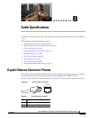
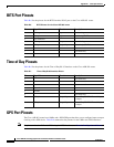
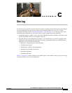
Figure B-2 shows the RJ-48C connector used by the T1/E1 ports on the TDM interface module on the
Cisco ASR 901 router.
Figure B-2 RJ-48C Connector
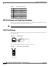
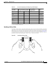
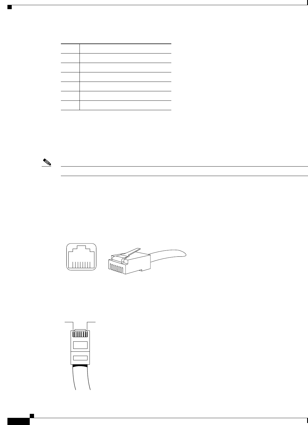
Figure B-3 shows the RJ-48C connector wiring for the T1/E1 cable.
Figure B-3 RJ-48-to-RJ-48 T1/E1 Cable Wiring
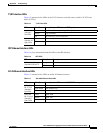
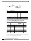
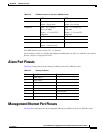
3 RX data+ RX B+
4 Not used TX C+
5 Not used TX C–
6 RX data– RX B–
7 Not used RX D+
8 Not used RX D–
Table B-1 RJ-45 Connector Pinouts
Pin FE Signal GE Signal
24939
8 7 6 5 4 3 2 1
RJ-48C connector
H11419
1
8