


1-4
Cisco ASR 901 Series Aggregation Services Router Hardware Installation Guide
OL-23778-01
Chapter 1 Introduction
Hardware Description
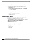
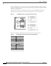
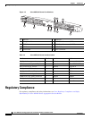
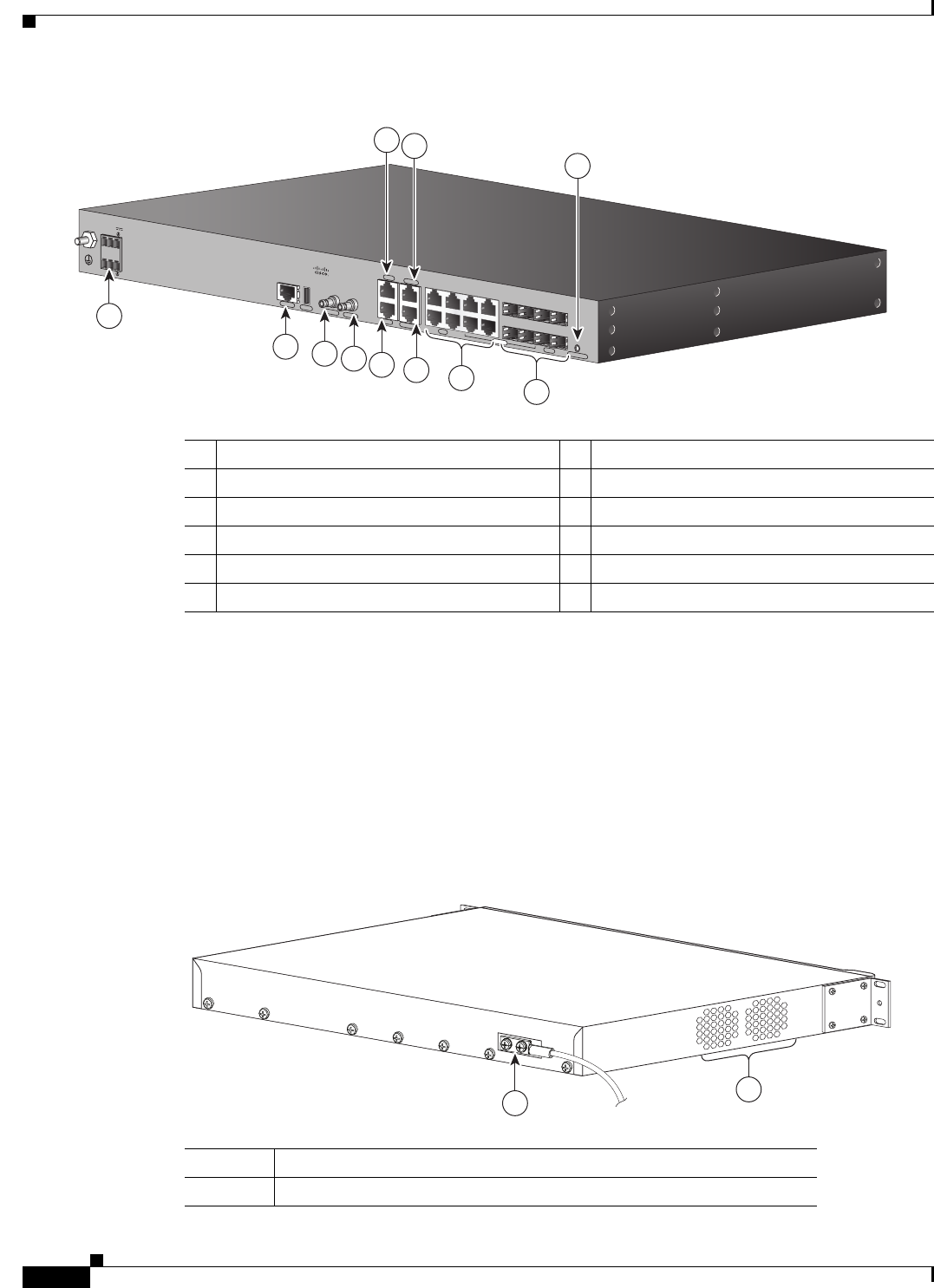
Figure 1-2 Cisco ASR 901 Router Ethernet Version Front View
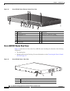
Cisco ASR 901 Router Rear View
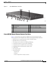
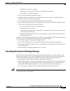
Figure 1-3 shows the rear view of the Cisco ASR 901 router including the orientation of the following
components:
• Two blowing fans
• Mounting point for the 2-hole lug. For more information, see the Connecting the Chassis Ground
and Power, page 3-5
Figure 1-3 Cisco ASR 901 Router—Rear View
1 ToD Port 7 BITS Port
2 Management Port 8 MINI-Coax Connector (1PPS)
3 Power LED 9 MINI-Coax Connector (10MHZ)
4 8 SFP Ports 10 Alarm
5 8 GE Ports 11 Power Connector
6 Console Port
SYSTEM
CONSOLE
BITS
1 PPS
MGMNT
TOD
10 MHz
ALARM
B
A
+
-
+
-
24V - 60V
3A
COMBO
SFP
NG-MRW-E
GE
USB
3
2
1
6
7
8
5
4
10
9
300097
11
1 Fan
2 Grounding Point Lug
282342
2
1