


3-13
Cisco ASR 901 Series Aggregation Services Router Hardware Installation Guide
OL-23778-01
Chapter 3 Installing the Cisco ASR 901 Mobile Wireless Router
Connecting Cables
Connecting the Network Cables
This section describes how to connect the following router interfaces:
• Connecting Gigabit Ethernet Interface Cables, page 3-13
• Connecting T1 and E1 Interface Cables, page 3-13
• Connecting SFP Cables, page 3-14
• Connecting Cables to the BITS Interface, page 3-14
• Connecting GPS Cables, page 3-14
• Connecting GPS Cables, page 3-14
• Connecting to the Management Ethernet Port, page 3-15
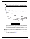
Connecting Gigabit Ethernet Interface Cables
The RJ-45 port supports standard straight-through and crossover Category 5 unshielded twisted-pair
(UTP) cables. Cisco Systems does not supply Category 5 UTP cables; these cables are available
commercially.
Complete the following steps to connect the cable to the router Gigabit Ethernet port:
Step 1 Confirm that the router is powered off.
Step 2 Connect one end of the cable to the GE port on the router.
Step 3 Connect the other end to the BTS patch or demarcation panel at your site.
For more information about Gigabit Ethernet connectors including pinouts, see “Gigabit Ethernet
Connector Pinouts” section on page B-1
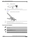
Connecting T1 and E1 Interface Cables
Complete the following steps to connect the cable to a router T1/E1 port:
Note You must close the relays on the card using the standalone subcommand. For more information, see the
Cisco ASR 901 Mobile Wireless Router Software Configuration Guide.
Step 1 Confirm that the router is powered off.
Step 2 Connect one end of the cable to the T1 or E1 (RJ-48C) port. Use a T1/E1 cable.
Step 3 Connect the other end to the BTS patch or demarcation panel at your site.
Step 4 Turn on power to the router (see “Powering On the Router” section on page 3-15 for more details).
For more information about T1/E1 connectors including pinouts, see “T1/E1 Port Pinouts” section on
page B-2.