


MODEL 113.24821 O, 113.248320,
1113.248440
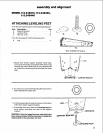
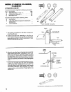
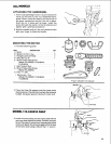
ATTACHING LEG SET
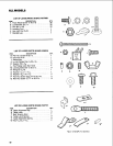
From the loose parts bag find the following hardware:
Item Description Qty.
A Truss Head Bolts 1/4.20x 1/2........... 32
B Lockwashers External 1/4 ............. 32
C Hex Nuts 1/4-20..................... 32
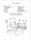
From the loose parts find the following items:
D Leg Channel ....................... 1
E Legs (with attached support brackets and
leveling feet) 4
F Lower Stiffeners .................... 4
_*NOTSHOWN TO SCALE
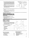
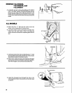
1. Lay a piece of cardboard on the floor to keep from
scratching the saw.
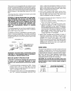
2. Position the basic saw assembly on the floor as
shown below. The back cabin et ofthe saw should be
laying flat on the floor. It may be necessary to have
someone help you lift the saw.
Switch
=_ont
Side ,/_/_J_//_1 __.Front Leg s Are
tt__._ _ Artacbed Here
_ Leg
J[ t_'/ \ Rear Legs Are
L_._/_Attached_ __ _ Here
\ Floor
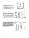
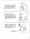
3. Mount the two front legs to the basic saw assembly
using truss head bolts, Iockwashers, and nuts.
Make sure that the four (4) holes in each corner of
the saw line up with the four (4) holes in the top of
each leg. At this time only put bolts through thesides
ofthe saw assembly notthe front. Onlyfinger tighten
nuts.
4. Position the leg channel inside the legset as shown.
Fasten the channel piece, leg, and saw together
with two (2) truss headbolts on each side. The
threaded section of the bolts should point towards
the inside of the basic saw assembly. Put a lock-
washer and hex nuton each bolt. Finger tighten nuts
atthis time.
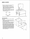
SAW
BAS E
LEG
!
LOCKWASHER
TRUSS
HEAD
SCREW
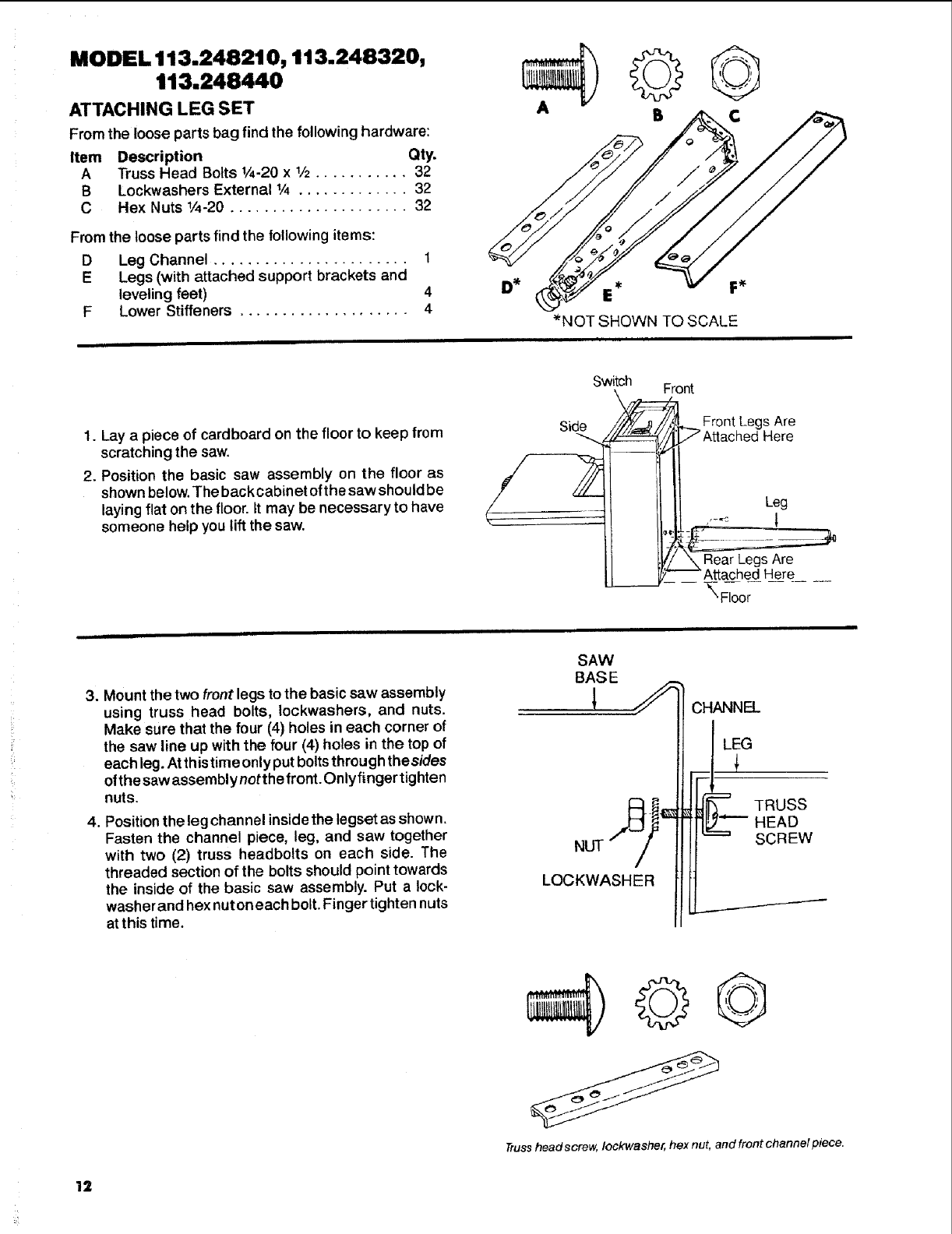
Trusshead screw, Iockwasher, hex nut, and front channel piece.
12