MODEL 113.248440 & 113.248510
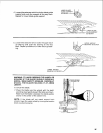
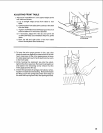
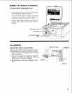
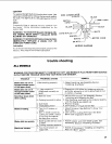
TILTING HEAD FOR BEVEL CUT
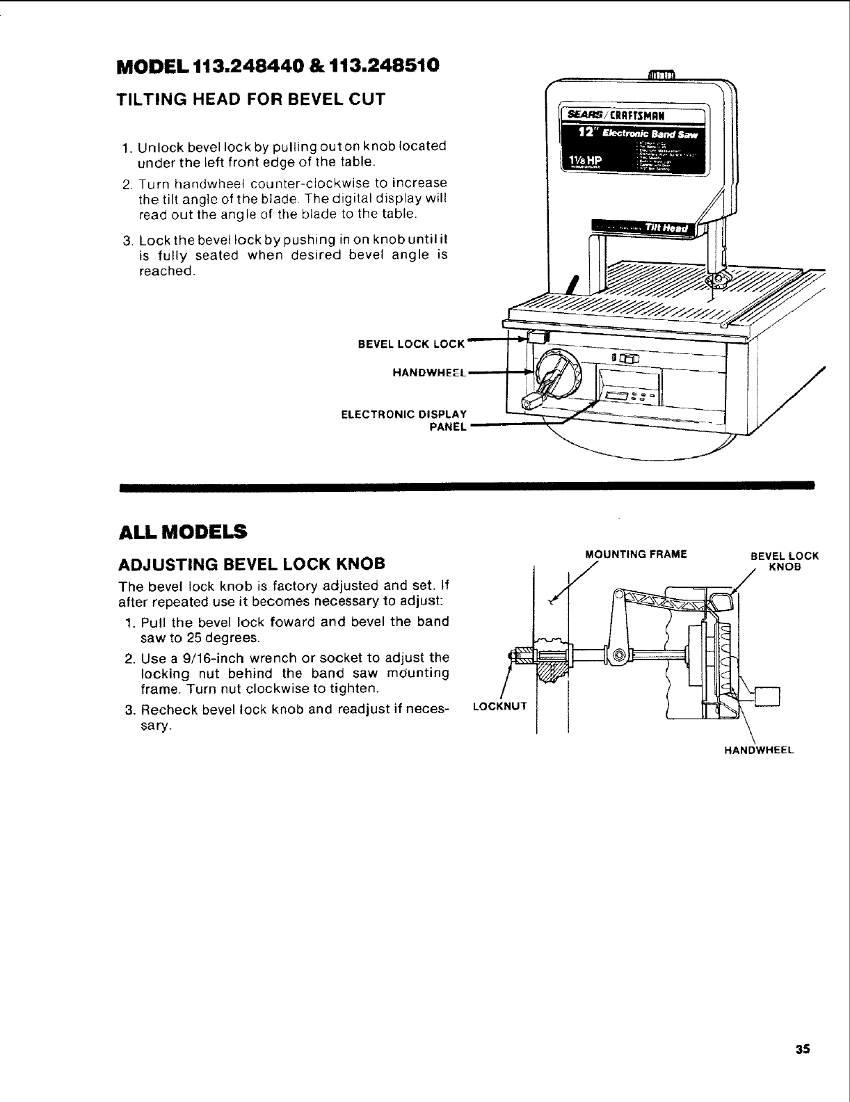
1, Unlock bevel lock by pulling outon knob located
under the left front edge of the table,
2. Turn handwhee4 counter-clockwise to increase
the tilt angle of the blade. The digital display will
read out the angle of the blade to the table.
3. Lock the bevel lock by pushing in on knob until it
is fully seated when desired bevel angle is
reached.
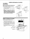
BEVEL LOCK
HANDWHEf
ELECTRONIC DISPLAY
PANEL
ALL MODELS
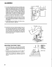
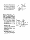
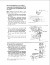
ADJUSTING BEVEL LOCK KNOB
The bevel lock knob is factory adjusted and set, If
after repeated use it becomes necessary to adjust:
1. Pull the bevel lock foward and bevel the band
saw to 25 degrees.
2. Use a 9/16-inch wrench or socket to adjust the
locking nut behind the band saw mdunting
frame. Turn nut clockwise to tighten.
3. Recheck bevel lock knob and readjust if neces-
sary.
LOCKNUT
MOUNTING FRAME
F
BEVEL LOCK
• KNOB
HANDWHEEL
35


