


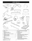
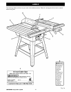

Assembly is best done in the area where the saw will be used. When you remove the table saw base, loose
parts, and hardware from the packing materials, check all items with the loose parts list and drawing. If you are
unsure about the description of any part, refer to the drawing. If any parts are missing, delay assembling until
you have obtained the missing part(s).
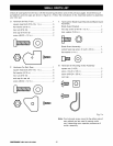
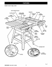
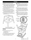
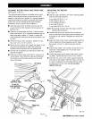
INSTALLING HANDWHEELS ON TABLE SAW
BASE
See Figure 6.
• Each handwheel bag contains a handwheel, a
screw (#10-24 x 1/2 in.), and a flat washer (#10).
• Align handwheels to the shaft ends that extend from
the front and right side of the table saw base. Match
the flat spots on the shaft and inside the handwheel.
Insert a screw and a flat washer in the handwheel
center and tighten with a 4 mm hex key.
HEIGHT
HANDWHEEL
BEVEL
HANDWHEEL
WASHER
TABLE
SAWBASE 8HAFT END 8CREW
Fig. 6
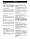
Note: tf you do not use the leg stand and mount the
saw table base on a bench instead of the legs, go
to the procedure for Assembfing Table Extensions.
Be sure the bench surface has an opening for
sawdust to fall through. The opening should be as
large as the opening in the bottom of the saw table
base. A height of 36 inches from the top of the
saw table to the floor is recommended.
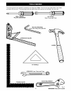
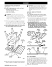
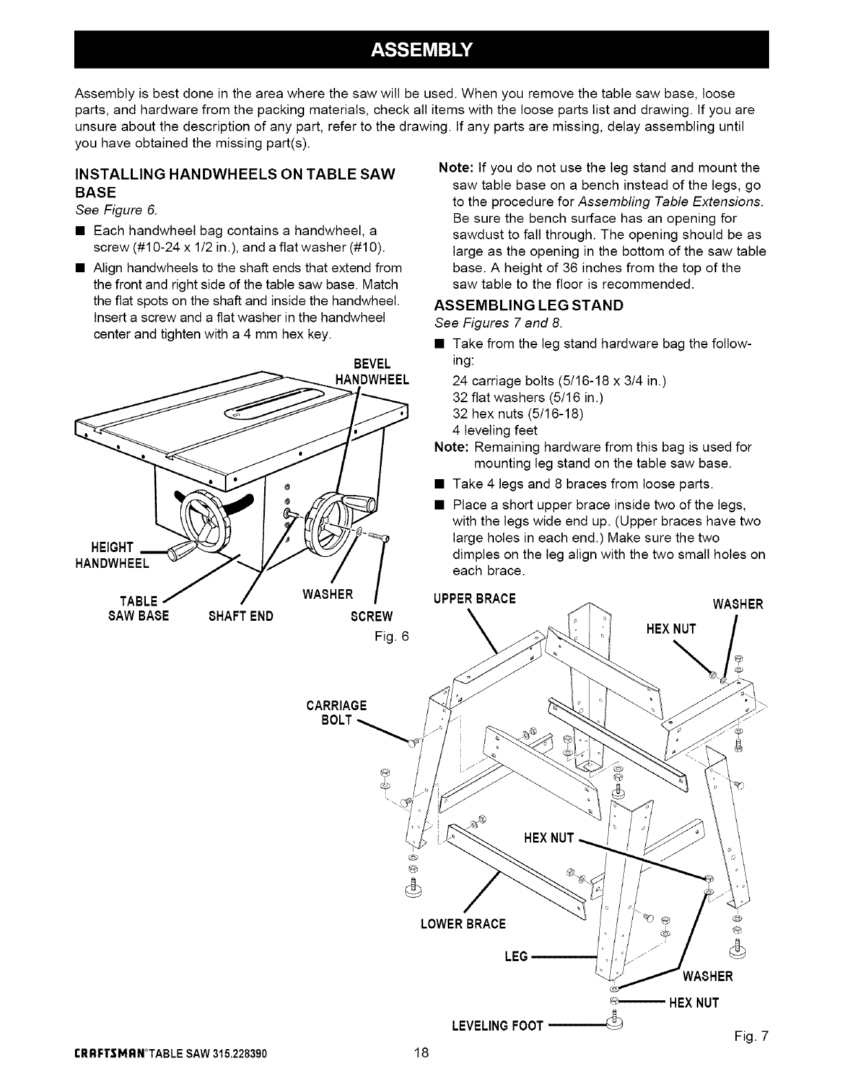
ASSEMBLING LEG STAND
See Figures 7 and 8.
• Take from the leg stand hardware bag the follow-
ing:
24 carriage bolts (5/16-18 x 3/4 in.)
32 flat washers (5/16 in.)
32 hex nuts (5/16-18)
4 leveling feet
Note: Remaining hardware from this bag is used for
mounting leg stand on the table saw base.
• Take 4 legs and 8 braces from loose parts.
• Place a short upper brace inside two of the legs,
with the legs wide end up. (Upper braces have two
large holes in each end.) Make sure the two
dimples on the leg align with the two small holes on
each brace.
UPPERBRACE
WASHER
HEXNUT
CARRIAGE
BOLT
rRRFTSMRN*TABLE SAW315.228390
@
®
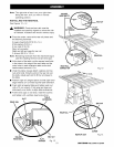
LOWERBRACE _#
LEG (_
WASHER
18
HEXNUT
LEVELINGFOOT
Fig. 7