


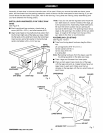
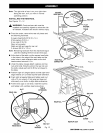
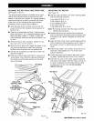
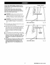
ALIGNING THE RIP FENCE AND FRONT RAIL
See Figures 17 and 18.
The rip fence scale indicator is installed on the right
side of the rip fence but can be removed and rein-
stalled on the left side if needed, tf a cutting operation
requires placing the rip fence on the left side of the
blade, and you find relocating the scale indicator
necessary, simply unscrew and re-attach it.
• Hook the back of the rip fence over the rear rail.
Lower the front of the rip fence into the groove on
the front rail.
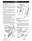
• Slide the rip fence back and forth, tt should move
freely with about 1/16 in. clearance between the rip
fence and table surface. If it doesn't, loosen the
nuts holding the front and rear rails and adjust it up
or down.
• When the fence rides smoothly, tighten all rail
hex nuts with a 12 mm wrench.
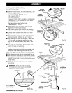
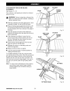
• Remove the rip fence and repeat the steps in the
two previous sections to install the remaining
sections of the front and rear rail assemblies.
• Use the rail connectors provided to join each rail
assembly together.
• Slide the rip fence back and forth to make sure it
moves freely. Also check the clearance between
the rip fence and the table surface on the other
side of the blade.
HOOKOVER REAR RAIL
REARRAILHERE
TO INSTALL
SCALEINDICATOR
ONLEFTBIDE
RIPFENCE
Fig. 17
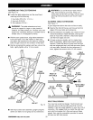
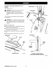
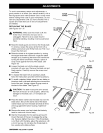
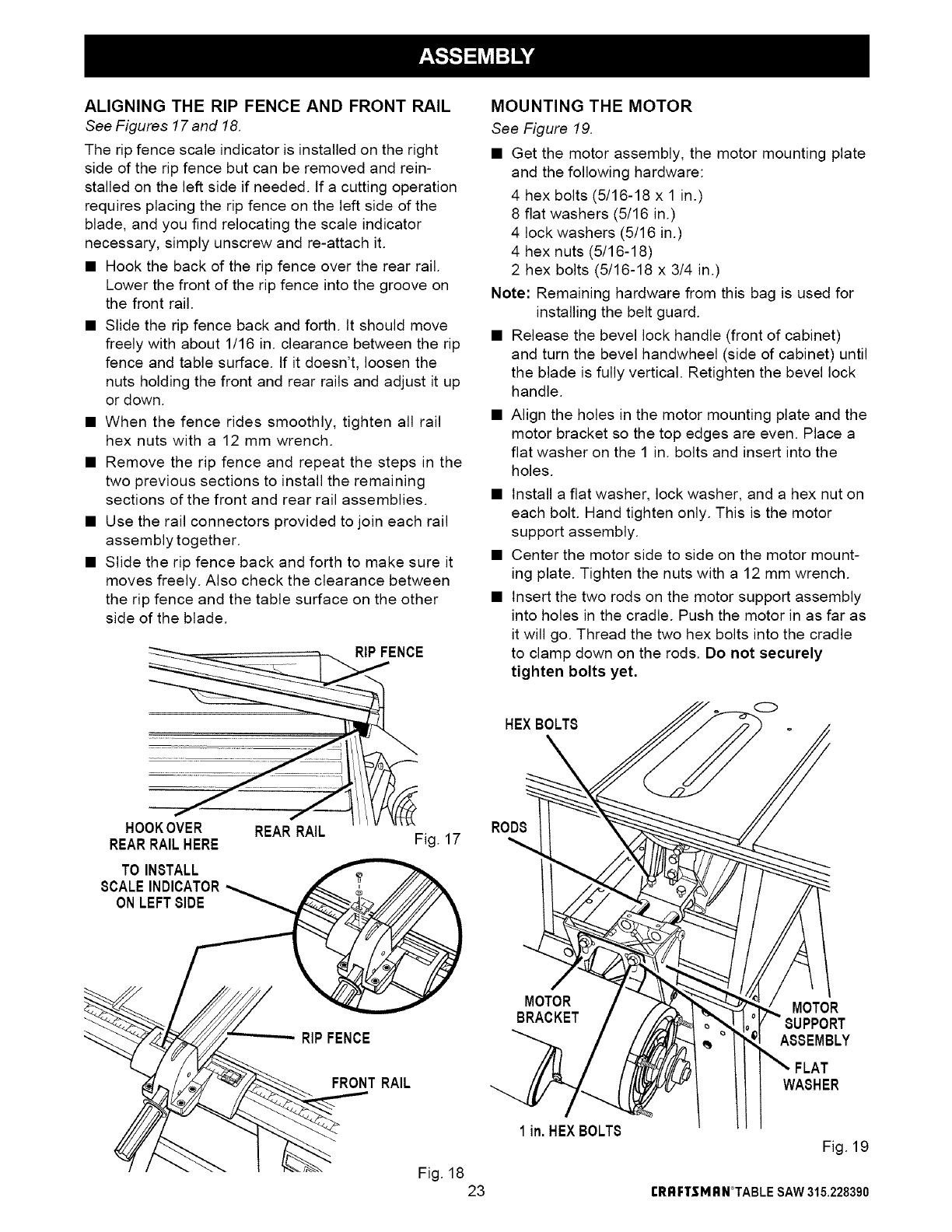
MOUNTING THE MOTOR
See Figure 19.
• Get the motor assembly, the motor mounting plate
and the following hardware:
4 hex bolts (5/16-18 x 1 in.)
8 fiat washers (5/16 in.)
4 lock washers (5/16 in.)
4 hex nuts (5/16-18)
2 hex bolts (5/16-18 x 3/4 in.)
Note: Remaining hardware from this bag is used for
installing the belt guard.
• Release the bevel lock handle (front of cabinet)
and turn the bevel handwheel (side of cabinet) until
the blade is fully vertical. Retighten the bevel lock
handle.
• Align the holes in the motor mounting plate and the
motor bracket so the top edges are even. Place a
fiat washer on the 1 in. bolts and insert into the
holes.
• Install a fiat washer, lock washer, and a hex nut on
each bolt. Hand tighten only. This is the motor
support assembly.
• Center the motor side to side on the motor mount-
ing plate. Tighten the nuts with a 12 mm wrench.
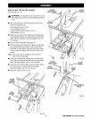
• Insert the two rods on the motor support assembly
into holes in the cradle. Push the motor in as far as
it will go. Thread the two hex bolts into the cradle
to clamp down on the rods. Do not securely
tighten bolts yet.
HEXBOLTS
0
RODS
RIPFENCE
MOTOR
BRACKET
MOTOR
SUPPORT
ASSEMBLY
FRONTRAIL
Fig. 18
23
1in. HEXBOLTS
WASHER
Fig. 19
rRRFTSMRN°TABLE SAW315.228390