


SERIAL INTERFACE (OPTION)
12 - 1
ETC00781(1) Series 100 e 10/2001
Rosemount Analytical
12. Serial Interface (Option)
12.1 Upgrading Serial Interface / Status Signals
(status signals only: PCB BSI 10, Catalog - No.: 43 001 590,
RS 232 - Interface: PCB BSI 10 with PCB SIF 232, Catalog - No.: CH 000 069
RS 485 - Interface: PCB BSI 10 with PCB SIF 485, Catalog - No.: CH 000 070,
see chapter 12.3.2, too)
Be sure to observe the safety measures !
P Switch off the analyzer and open the housing (see 23.)
P Mount the circuit board to the threated bolts at the rear panel and fix it using the
washers and the screws.
P Connect the signal cable to connector J9 on BKS paying attention to the coding pin.
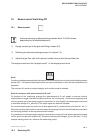
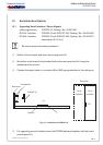
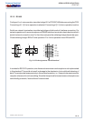
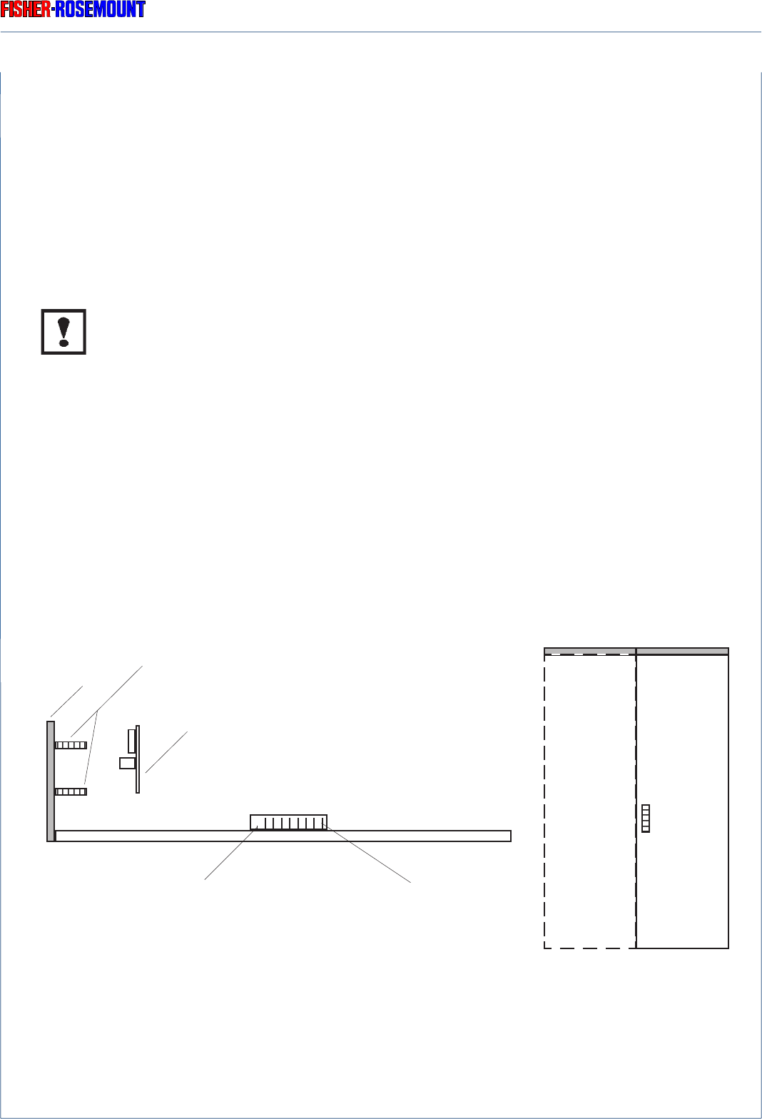
RETROFITTING
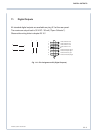
Fig. 12-1: Installation of PCB BSI 10
P For upgrading a serial interface insert the EPROM delivered together with the board
(see chapter 28.).
J 9
PCB BSI 10
Threated bolt
Rear panel
J 9
Rear panel
1
Code pin
1/4 19"
analyzers
1/2 19"
analyzers