


24 - 3
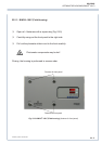
REPLACEMENT AND CLEANING OF PHOTOMETRIC COMPONENTS
ETC00781(4) Series 100 e 02/2004
24.3 Cleaning of Analysis Cells and Windows
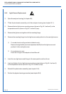
24.3.1 Removal of Analysis Cells
P Open the analyzer housing (cf. chapter 23).
P Take the photometer assembly out of the analyzer housing (see chapter 24-1).
a) For analysis cells of lengths 1 mm and 7 mm
P Remove the clamp (Fig. 24-2, Item 2).
P Remove the clamping collar and the filter cell with signal detector assembly.
b) For analysis cells of lengths 50 mm - 200 mm:
P Remove the clamp (Fig. 24-2, Item 3).
P Remove the filter cell with signal detector assembly.
P Remove the mounting screws shown in Fig. 24-2, Item 4.
P Remove the analysis cell body from the chopper housing.
Only analyzers with gas detector:
P Remove preamplifier from analysis cell
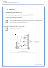
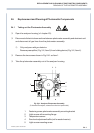
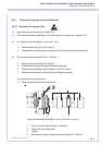
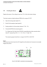
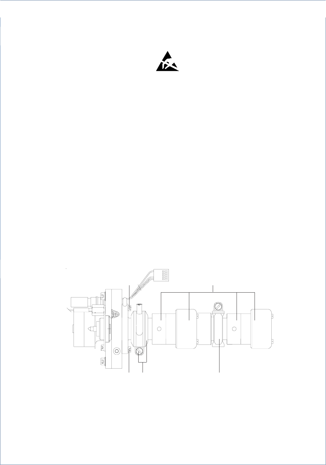
Fig. 24-2: Photometer Assembly (2 channel photometer, side view)
1 Filter cell with signal detector assembly
2 Clamp with clamping collar
3 Clamp
4 Mounting screws for analysis cells of lengths 50 - 200 mm
REMOVAL OF ANALYSIS CELLS
1
3
4
4
2