


REPLACEMENT AND CLEANING OF PHOTOMETRIC COMPONENTS
24 - 2
ETC00781(4) Series 100 e 02/2004
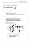
24.2 Light Source Replacement
P Open the analyzer housing (cf. chapter 23).
P TTake the photometer assembly out of the analyzer housing (see chapter 24.1).
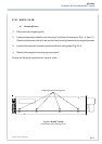
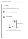
P Remove the two light source mounting screws (shown in Fig. 24-1 as Item 5) or the
temperature sensor (shown in Fig. 24-1 as Item 3) resp.
P Remove the light source together with its mounting flange.
P Remove the mounting flange from the light source and position it on the new light source.
P For sealed version with pyroelectrical detector only:
Remove the tight baffle (zero level adjustment baffle) from the light source and
position it in the new light source.
P For sealed version only:
Place the O-rings on the adapter cell and filter cell.
P Insert the new light source and flange in the same position as the old one.
P Insert and tighten the two light source mounting screws (shown in Fig. 24-1 as Item 5)
or the temperature sensor (shown in Fig. 24-1 as Item 3) resp.
P Reinstall the photometer assembly (see chapter 24.5).
P Perform the physical zeroing procedure (see chapter 24.6).
LIGHT SOURCE REPLACEMENT