


PREPARATION
5 - 14
ETC00781(4) Series 100 e 02/2004
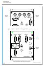
b) Optional Signal Lines
This are analog outputs, digital inputs/outputs and serial interfaces.
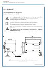
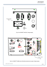
P Open the analyzer's front door.
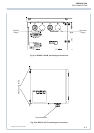
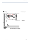
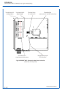
P Insert the cable through the cable glands (Fig. 5-6 and 5-5) into the housing.
Connection is to be done to the respective terminal strips (Fig. 5-7 and 5-8).
Assignment see chapter 2.
Cables to external dataprocessing have to be double-insulated against mains
voltage for analyzer BINOS
®
100 F !
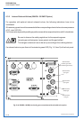
ADDITIONAL HINTS ON BINOS
®
100 F (FIELD HOUSING)
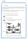
Use only shielded cables for signal lines! To ensure proper electromagnetic
compatibility (EMC) it is recommended to follow the installation steps given
below.
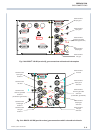
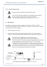
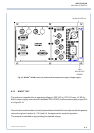
Cable Gland Assembly Instruction
for Shielded Cables
All unused cable glands need to be sealed using a sealing plug
(part no. ETC00791 or similiar)
Unused cable gland openings in the enclosure need to be covered using a
special screw (part no. ETC 000790 or similiar).
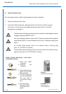
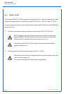
ETC00791
Cable gland sealing plug
ETC00790
Cable gland allen
screw sealing plug
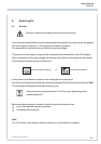
3. Feed cable through
gland nut and into
fixing element
4. Put the shielding
net over the element
the way that it
covers the o-ring 2
mm.
1. Strip the cable
insulation
2. Uncover the
shielding
5. Stick the fixing
element into the
neck and fix the
gland.