


10 Micro Motion 3098 Gas Specific Gravity Meter
Installation Procedure
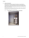
The 3098 specific gravity meter is contained inside an IP-rated enclosure (which provides thermal
insulation) and a mounting system (consisting of a bracket and feet) to fix the unit in place. While this
structure is designed to minimize damage due to shocks, the box and unit must not be dropped.
Dropping the 3098 specific gravity meter either inside or outside its enclosure will damage the meter.
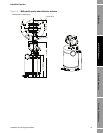
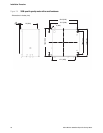
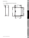
Contained inside the enclosure are four box feet which, when attached to a vertical wall will hold the
housing. A set of instructions on how to attach these feet is included inside the box. Enclosure
dimensions are in Section 2.7.
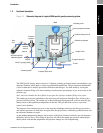
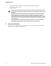
2.3.2 Connections
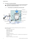
There are four connections that need to be made to the 3098 specific gravity meter: three gas pipeline
connections and one electrical connection through an IP-rated cable gland. The gas pipeline
connections take the form of ¼" Swagelok bulkhead fittings, and are used for the gas input, gas output
and pressure relief lines.
Each connection is labelled.
A gas density meter is used as the measuring instrument in the 3098 specific gravity meter and needs
to be connected inside the enclosure. All wiring should be connected through the cable gland to
maintain the enclosure’s overall protection to dust and water ingress.
At all stages during calibration and operation, the 3098 specific gravity meter is designed to function
with the enclosure sealed. This allows the unit to operate in the condition of thermal equilibrium,
which is essential for accurate measurement.
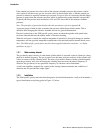
2.3.3 Coalescing filter
Ensure that the coalescing filter (as supplied) is fitted into the gas supply line to the 3098 meter. This
MUST be done in order to comply with the ATEX/IECEx approval requirements.
2.4 Electrical connections and safety barriers / galvanic isolators
When the 3098 specific gravity meter is mounted in a hazardous area, the electrical connections to the
meter must conform to stringent conditions. For electrical connections between the meter and its
associated flow computer/signal converter, for ATEX/IECEx installations see the ATEX/IECEx Safety
Instructions booklet (available at www.micromotion.com) and for CSA installations see Appendix D.
Electrical cable connection to the 3098 specific gravity meter is made to the terminal block inside the
resonator electronics housing (for example, inside the enclosure). Poor connection to the terminals
will prevent correct operation but will not damage the unit – provided that safety barriers or galvanic
isolators are included in the circuit for hazardous areas or the maximum power supply does not
exceed the 33 V maximum limit (as described in Chapter 3).
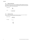
The power supplied to the meter terminals should be in the range of 15.5 to 33 Vdc with the average
current drawn by the unit being < 20 mA. If the current consumption exceeds this value, the polarity
of the connections should be checked.
A full description of how to connect the 3098 specific gravity meter to a signal converter/flow
computer is given in Chapter 3.
Connecting the gas input line to the wrong bulkhead fitting might result in damage.