


Installation and Configuration Manual 13
Installation Procedure
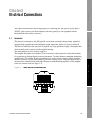
Installation Procedure Accuracy ConsiderationsElectrical ConnectionsIntroduction
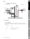
Purge cycling
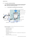
10. Close valve C.
11. When Control Pressure Indicator is at the desired value, shut valve A and open valve F. Allow
the gas to vent to atmospheric pressure.
12. Close valve F and open valve A.
13. When Control Pressure Indicator is at the desired value, shut valve A and open valve F. Allow
the gas to vent to atmospheric pressure.
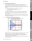
Steps 12 and 13 define the purging cycle required for setting up the reference chamber gas in
the 3098 specific gravity meter. The number of times that this procedure should be repeated
depends upon the gas regulator pressure used and is defined by:
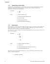
14. Once the required number of cycles has been performed, close valve F and open valve A.
15. When the desired gas pressure inside the chamber has been reached (as shown by the Control
Pressure Indicator) shut the chamber valve.
3098 specific gravity meter calibration using two known gases
16. Close valve A.
17. Connect the first calibration gas bottle to the pipework and set the pressure to be typically 25%
above that inside the reference chamber.
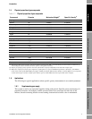
18. Open valve B.
19. Ensure valve C is open and allow gas to flow until the time period as measured by the signal
converter/flow computer is stable to ±1 ns or better (the typical stability will be better than
this). [For the required electrical connections see Chapter 3]
20. Note this time period (τ
1
) together with the certified SG from the bottle of gas (SG
1
).
21. Shut valve B.
22. Replace the first calibration gas bottle with the second calibration gas bottle.
23. Set pressure to typically 25% above that inside the reference chamber and open valve B.
24. Allow gas to flow until the time period shown by the meter is stable to ±1 ns or better.
25. Note this time period (τ
2
) and the certified SG from the bottle of gas (SG
2
).
26. Apply these noted numbers into equations (1) and (2) below:
You can enter this information directly into the Calibration Certificate example in Section 4.4.
For an online version of this certificate, download the Calibration Certificate Excel file at
www.micromotion.com (located on the 3098 products page) or access the calcert.xls file on
the floppy disk shipped with the product.
DO NOT open the chamber valve again. The gas now inside the 3098 chamber is the line reference
gas.
⎥
⎦
⎤
⎢
⎣
⎡
pressure regulatormax
7 x 3
= cycles purge of Number
() ( )
()
(2)
(1)
2
1210
2
2
2
1
21
2
τ
ττ
KSGK
SGSG
K
−=
⎥
⎦
⎤
⎢
⎣
⎡
−
−
=