


Installation and Configuration Manual 31
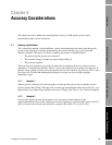
Accuracy Considerations
Installation Procedure Accuracy ConsiderationsElectrical ConnectionsIntroduction Installation Procedure Accuracy ConsiderationsElectrical ConnectionsIntroduction Installation Procedure Accuracy ConsiderationsElectrical ConnectionsIntroduction Installation Procedure Accuracy ConsiderationsElectrical ConnectionsIntroduction
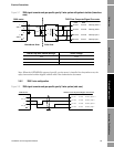
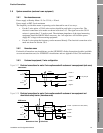
Example 1
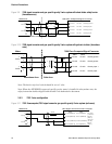
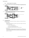
Example 2
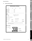
4.2 Calibration (for non-natural gas applications)
The instrument is supplied with its reference chamber empty and thus in an un-calibrated condition.
After installation on site it is necessary to decide what reference chamber pressure to use, and then to
charge and calibrate the instrument as described in Section 2.6.
Some examples of how to calculate these reference chamber pressures are given in Section 4.1.1 and
Section 4.1.2, which show the best pressures for a natural gas and a N
2
/CO
2
mix application.
Once this has been done, the gases to be used for calibration need to be defined. The calibration gases
to be used must be of known specific gravities and substantially represent the properties of the line
gas to be measured (for example, compressibility, viscosity) For example, if measuring a natural gas
which is substantially methane and carbon dioxide, then these two gases in their pure forms or at
defined specific gravities should be used in the calibration.
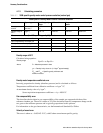
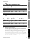
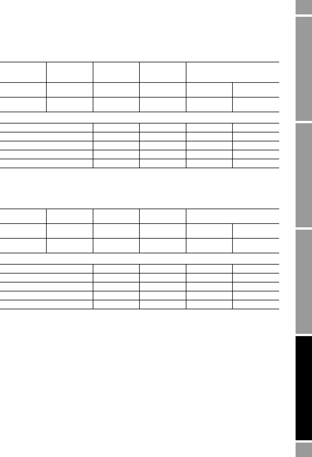
Table 4-2 3098 specific gravity meter control pressure selection (natural gas)
Date: 24th June
1997
Type of gas:
Natural Gas
Specific gravity
range: 0.55 to
0.8
3098 serial no.:
000124
Temperature coefficient of density
meter: –0.0003
kg/m3
/°C
Control pressure
at 20°C
(lb/in
2
abs.)
(bar abs.)
18
1.2
30
2
60
4
100
7
Density range at
20°C
(kg/m
3
) 0.79–1.15 1.32–2.0 2.66–3.8 4.58–6.72
Measurement errors (% of FS specific gravity/°C) due to:
Density meter temperature coefficient –0.026 –0.016 –0.008 –0.004
Gas compressibility of sample gas ±0.0003 ±0.0003 ±0.001 ±0.002
Velocity of sound in sample gas –0.003 –0.003 –0.003 –0.003
Reference chamber/relief valve +0.007 +0.007 +0.007 +0.007
Total error –0.022 –0.012 +0.003 to –0.005 +0.000 to –0.002
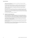
Table 4-3 3098 specific gravity meter control pressure selection (N
2
CO
2
mix)
Date: 28th July
1997
Type of gas:
N
2
/CO
2
mix
Specific gravity
range: 1.0 to 1.5
3098 serial no.: Temperature coefficient of density
meter: –0.0003
kg/m3
/°C
Control pressure
at 20°C
(lb/in
2
abs.)
(bar abs.)
18
1.2
30
2
60
2
100
7
Density range at
20°C
kg/m
3
0.79–1.15 1.32–2.0 2.66–3.8 4.58–6.72
Measurement errors (% of FS specific gravity/°C) due to:
Density meter Temperature coefficient –0.026 –0.016 –0.008 –0.004
Gas compressibility of sample gas ±0.0003 ±0.0003 ±0.001 ±0.002
Velocity of sound in sample gas –0.003 –0.003 –0.003 –0.003
Reference chamber/relief valve +0.007 +0.007 +0.007 +0.007
Total error –0.014 –0.006 +0.006 to –0.010 +0.015 to –0.015