


Installation and Configuration Manual 23
Electrical Connections
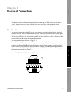
Installation Procedure Accuracy ConsiderationsElectrical ConnectionsIntroduction
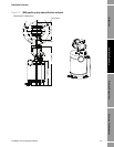
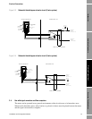
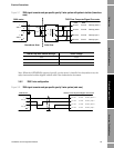
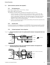
Figure 3-7 7950 signal converter and gas specific gravity 2-wire system with galvanic isolator (hazardous
area)
Note: When the ATEX/IECEx-approved specific gravity meter is installed in a hazardous area, the
safety instruction booklet shipped with the unit is the authoritative document.
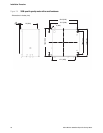
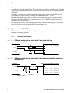
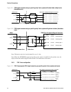
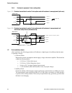
3.5.2 7950 3-wire configuration
Figure 3-8 7950 signal converter and gas specific gravity 3-wire system (safe area)
3098 meter
1
+
SIG A
2
-
3
+
SIG B
4
-
MTL 5532
4
5
14
13
Hazardous Area Safe Area
Density power +PL10/1
Ch.3
PL10/4
PL10/3
PL10/2
PL10/5
Ch.4
PL10/8
PL10/7
PL10/6 Density input +
Density input -
Density power -
7950 Flow Computer/Signal Converter
10k
1
12
11
2kR
ZD1
Barrier trip level switch settings Zener voltage
12V 6.2V
6V 13V
3V 16V
3098 meter
1
+
SIG A
2
-
3
+
SIG B
4
-
7950 Flow Computer/Signal Converter
Density power +PL10/1
Ch.3
PL10/2
PL10/3
PL10/4
PL10/5
Ch.4
PL10/6
PL10/7
PL10/8
Density input +
Density input -
Density power -