


20 Micro Motion 3098 Gas Specific Gravity Meter
Electrical Connections
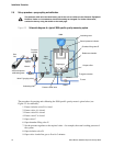
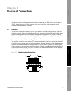
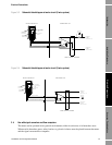
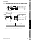
Figure 3-2 Interconnection diagram
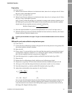
3.2 EMC cabling and earthing
To meet the EC Directive for EMC (Electromagnetic Compatibility), it is recommended that the meter
be connected using a suitable instrumentation cable and earthed through the meter body and
pipework.
The instrumentation cable should have an individual screen, foil, or braid over each twisted pair and
an overall screen to cover all cores. Where permissible, the overall screen should be connected to
earth at both ends (360° bonded at both ends). The inner individual screen should be connected at
only one end, the controller end (for example, signal converter end).
Note: For intrinsic safety, termination of the inner individual screen(s) to earth in the hazardous area
is not generally permitted.
Note: Use suitable cables that meet BS5308 multi-pair instrumentation Types 1 or 2.
3.3 Certificate conditions for hazardous areas
For details of hazardous area installations, see the ATEX/IECEx Safety Instructions booklet (available
at www.micromotion.com) for ATEX/IECEx installations and see Appendix D for CSA installations.
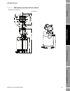
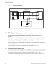
The 3098 specific gravity meter can be electrically connected in either a 2-wire or 3-wire
configuration. A schematic block diagram of these two types is given in Figure 3-3 and Figure 3-4.
INTERCONNECT PCB
78121503
TERMINAL PCB
78121502
SPOOLBODY
78121201
AMPLIFIER PCB
78121501
PICK UP
COIL
DRIVE
COIL
BN PL1
13 20
2
BN
BN
I/P +
R PL2
14 19
3
O
R
I/P -
O PL5
16 18
4
R
O
O/P +
Y PL6
15 17
5
B
Y
O/P -
R PL3
22
V +
G PL4
21
V -
23
12 4 3
- B+ -
SIG BSIG A
O PL7
FREQ. OUT