


Installation and Configuration Manual 3
Introduction
Installation Procedure Accuracy ConsiderationsElectrical ConnectionsIntroduction
1.3 Functional description
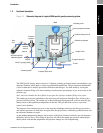
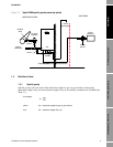
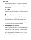
Figure 1-2 Schematic diagram of a typical 3098 specific gravity measuring system
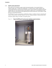
The 3098 specific gravity meter consists of a vibrating cylinder gas density meter surrounded by a gas
reference chamber, which helps to achieve good thermal equilibrium. The gas reference chamber has
a fixed volume that is initially pressurized with the actual line gas. It is then sealed by closing the
reference chamber filling valve, thus retaining a fixed measure and quantity of gas, now known as the
reference gas.
Note: Once the chamber has been filled, do not open the reference chamber filling valve again.
The sample gas enters the instrument at the enclosure side and passes through a filter, followed by a
pressure-reducing orifice. The sample gas is then fed through input pipework so that it enters the gas
density meter at the equilibrium temperature of the unit. The gas then flows down to a pressure
control valve chamber.
The pressure of the reference gas acts on the separator diaphragm and forces the line gas pressure to
rise until the pressures on both sides are equal, thus the gas pressures within the gas density meter and
the reference chamber are equal.
As the ambient temperature changes, the pressure of the fixed volume of reference gas will change as
defined by the Gas Laws. This change in pressure will affect the sample gas pressure within the gas
density meter such that the temperature and pressure changes are self-compensating.
Gas
line
3098
Pressure
regulator
Insulating cover
Control pressure indicator
Chamber filling valve E
Reference chamber
Output orifice
To signal converter
To vent
Outlet
Valve C
Valve B
Valve F (purging valve)
Vent and input for
calibration gases
Isolation
valve D
Valve A
Input
orifice
Filter
Pressure relief valve
Diaphragm
Coalescing filter