


42 Micro Motion 3098 Gas Specific Gravity Meter
Maintenance and Fault Finding
6. Re-assembly is the reverse of steps 2 and 1 above.
Note: Once the unit has been replaced into its enclosure, a leak check must be performed before
on-line operation.
5.4.6 Further servicing of the density meter (Figure 5-5)
Once the density meter has been removed from the 3098 specific gravity meter metalwork and the
electronics housing removed, the unit can be further serviced by following the instructions below:
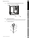
1. Referring to Figure 5-2, remove the six screws (item 3) which secure the cylinder housing
(item 2) to the mounting housing (item 1).
2. Exercising great care, ease off the cylinder housing in an axial direction, allowing access to the
cylinder/spoolbody assembly.
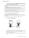
3. Carefully lift off the cylinder (item 4) and clean by lightly wiping with a lint-free tissue soaked
in an appropriate solvent.
4. Again, exercising great care, ease out the spoolbody (item 5). Clean the spoolbody and
examine for corrosion.
If no corrosion or other damage is apparent on any of the piece parts, the instrument may be
reassembled in reverse order. During re-assembly of the sensing element, special attention is required
to correctly orientate the cylinder/spoolbody combination (see Figure 5-5).
Re-fit the meter to the 3098 specific gravity meter, by following the operations above in reverse order,
making sure that the scribe marks align as shown in Figure 5-5.
Note: It is recommended that O-rings be renewed during re-assembly and lightly coated with silicone
grease.
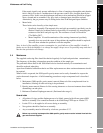
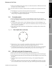
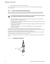
Figure 5-5 Spoolbody/cylinder alignment
The cyclinder wall is fragile. Great care must be shown during the removal, handling, and refitting
of the cyclinder and its housing. Hold only by the clamping section.
Scribe Lines to be
aligned.