


22 Micro Motion 3098 Gas Specific Gravity Meter
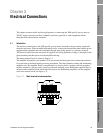
Electrical Connections
When operating in a safe area with a 3-wire system, the line resistance between meter and signal
converter must be greater than 40 ohms. This can be achieved by placing a suitable resistor in the line
or by using the inherent resistance of the cable used (if the resistance per km and length of cable used
is sufficient).
Given these conditions, we recommend that the maximum cable length between the 3098 specific
gravity meter and signal converter – assuming a BS5308 standard cable – is 2 km.
When the 3098 specific gravity meter is installed in a hazardous area, see the ATEX/IECEx Safety
Instructions booklet (available at www.micromotion.com) for ATEX/IECEx installations and see
Appendix D for CSA installations.
For the purposes of clarity, all wiring diagrams describing a safe area setup using the 3-wire system
have had a 40-ohm resistor placed into the +24 V power supply line.
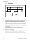
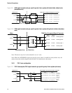
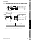
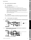
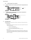
3.5 System connections (7950/7951)
The density and power connections to the 3098 specific gravity meter in safe and hazardous areas are
shown in the following diagrams:
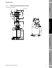
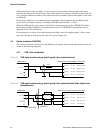
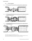
3.5.1 7950 2-wire configuration
Figure 3-5 7950 signal converter and gas specific gravity 2-wire system (safe area)
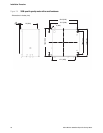
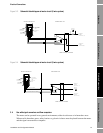
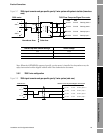
Figure 3-6 7950 signal converter and gas specific gravity 2-wire system with shunt-diode safety barrier
(hazardous area)
3098 meter
1
+
SIG A
2
-
3
+
SIG B
4
-
330R
7950 Flow Computer/Signal Converter
Density power +PL10/1
Ch.3
PL10/2
PL10/3
PL10/4
PL10/5
Ch.4
PL10/6
PL10/7
PL10/8
Density input +
Density input -
Density power -
3098 meter
1
+
SIG A
2
-
3
+
SIG B
4
-
MTL 787 (+ve)
3
4
1
2
Hazardous Area
Safe Area
7950 Flow Computer/Signal Converter
Density power +PL10/1
Ch.3
PL10/2
PL10/3
PL10/4
PL10/5
Ch.4
PL10/6
PL10/7
PL10/8
Density input +
Density input -
Density power -