


28 Micro Motion 3098 Gas Specific Gravity Meter
Electrical Connections
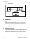
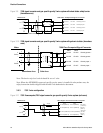
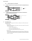
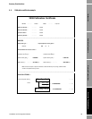
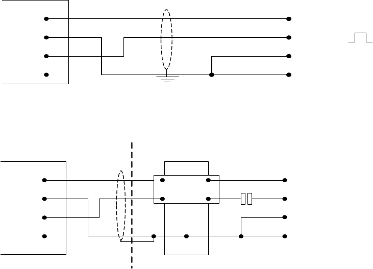
3.6.4 Customer's equipment, 3-wire configuration
Figure 3-19 Electrical connections for meter 3-wire option used with customer’s own equipment (safe area)
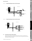
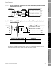
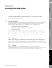
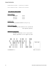
Figure 3-20 Electrical connections for meter 3-wire option used with customers’ own equipment and
shunt-diode safety barrier (hazardous area)
3.7 Post-installation checks
After installation, the following procedure will indicate to a high degree of confidence that the meter
is operating correctly.
1. Electrical Check
Measure the current consumption and the supply voltage at the meter amplifier. This should be
within the following limits:
• 15.5 Vdc to 33 Vdc (Safe Areas)
• 15.5 Vdc to 24 Vdc (Hazardous Areas)
• 10 mA at 24 V dc input (Nominal input current)
• 17 mA maximum (Safe and Hazardous Areas, any input voltage)
2. Stability Check
Check the stability of the frequency output signal using a period meter on a 1000-cycle count.
The measurement scatter should be within ±2 ns. If this value is exceeded, it is likely that dirt
is present on the sensing element. This test may be performed at any gas density, provided that
the latter is not changing.
3098 meter
1
+
SIG A
2
-
3
+
SIG B
4
-
Power +
Power -
Signal +
Signal -
6V pk to pk
3098 meter
1
+
SIG A
2
-
3
+
SIG B
4
-
MTL 787 (+ve)
3
4
1
2
Hazardous Area Safe Area
Power + (24.25 to 27V DC, 30mA)
Power -
Signal +
Signal -
1nF