


Installation and Configuration Manual 37
Maintenance and Fault Finding
SpecificationMaintenance and Fault Finding
If the erratic signal is only present while there is a flow of sample gas through the unit, then the
fault is likely to be due to a malfunction of the pressure control valve, brought about by the
presence of dirt. In this case the diaphragm (and hence valve mechanism) should be stripped
down, cleaned and re-assembled. Any poor seals or damaged parts should be replaced.
Alternatively, the gas pressure may be falling below that of the designed input condition.
• Meter faults
These faults can be found by a few simple tests:
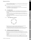
• Spoolbody Assembly: The magnetic drive and pick-up assembly (spoolbody) can be
checked visually for problems and also electrically for continuity, by measuring the
resistance of the drive and pick-up coils. The resistance of each coil should be
(72±10)Ω at 20°C.
• Meter Amplifier: If careful examination of the sensing element and spoolbody
assembly does not reveal the cause of the problem, the amplifier should be replaced.
This will show whether the problem is with the amplifier.
Note: A check of the amplifier current consumption is a good indicator of the amplifier’s health. A
further test to check the amplifier is to change the supply voltage across its operating range and check
that the time period does not change.
5.4 Maintenance
The supplied coalescing filter should be checked regularly for liquid and particulate contamination.
The frequency of checking is dependent upon the condition of the sample gas.
The particulate filters fitted in the 3098 should also be checked routinely for contamination and
should be replaced when dirty.
Apart from scheduled calibration checks and filter replacements no other routine maintenance should
be required.
When a fault is suspected, the 3098 specific gravity meter can be easily dismantled to expose the
section that needs inspection. A full dismantling procedure to major component level is described
below.
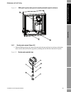
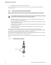
1. Main meter (3098 specific gravity meter) removal: Removal of the complete unit from its
installation, allowing all other servicing to be performed.
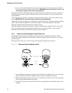
2. Density meter removal: Removal of the sensing element to a clean environment where further
dismantling can take place.
3. Reference Chamber Diaphragm removal: (Performed after stage 1).
General notes
• All gaskets, O-rings and the diaphragm are to be lightly greased with silicone grease MS4
before re-assembly. Gas connection threads to be sealed using PTFE tape or Loctite 572.
• Loctite 221 is to be applied to all screws during re-assembly.
• New gaskets should be fitted on re-assembly.
• Any re-assembly must be followed by a leak test, procedure 5.2.7.
Before any servicing is attempted the 3098 specific gravity meter must be isolated from both the
gas and electrical supplies.