


Installation and Configuration Manual 27
Electrical Connections
Installation Procedure Accuracy ConsiderationsElectrical ConnectionsIntroduction
3.6 System connections (customer’s own equipment)
3.6.1 Non-hazardous areas
Power supply to Density Meter: 15.5 to 33 Vdc, < 20 mA.
Power supply to PRT: 5 mA maximum
The frequency at which the meter is operating can be detected in one of two ways:
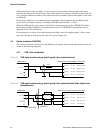
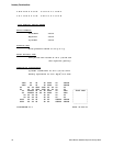
• For the 2-wire option, a 330 Ω series resistor should be used in the +ve power line. The
electrical connections to be made are shown in Section 3.6.3. The signal across the 330 Ω
resistor is greater than 2 V peak-to-peak. The minimum impedance of the signal measuring
equipment should be 500 kΩ. Where necessary, the 1 nF capacitors will block the power
supply DC voltage to the measuring equipment.
• For the 3-wire option, the frequency can be measured directly. The electrical connections to be
made are shown in Section 3.6.4.
3.6.2 Hazardous areas
For details of hazardous area installations, see the ATEX/IECEx Safety Instructions booklet (available
at www.micromotion.com) for ATEX/IECEx installations and see Appendix D for CSA installations.
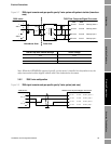
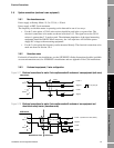
3.6.3 Customer's equipment, 2-wire configuration
Figure 3-17 Electrical connections for meter 2-wire option used with customers’ own equipment (safe area)
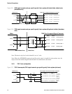
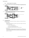
Figure 3-18 Electrical connections for meter 2-wire option used with customers’ own equipment and
shunt-diode safety barrier (hazardous area)
3098 meter
1
+
SIG A
2
-
3
+
SIG B
4
-
330R
1nF
1nF
Power +
Power -
Signal +
Signal -
2.3V pk to pk
3098 meter
1
+
SIG A
2
-
3
+
SIG B
4
-
MTL 787 (+ve)
3
4
1
2
Hazardous Area Safe Area
Power + (24.25 to 27V DC, 30mA)
Power -
Signal +
Signal -
1nF
1nF
10kΩ