


12 Micro Motion 3098 Gas Specific Gravity Meter
Installation Procedure
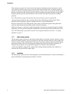
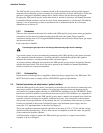
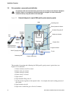
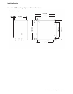
2.6 Set-up procedure – purge cycling and calibration
Figure 2-2 Schematic diagram of a typical 3098 specific gravity measuring system
The procedure for purging and calibrating the 3098 specific gravity meter is given below (see
Figure 2-2 for reference):
1. Ensure isolation valve D is closed.
2. Ensure valve A is closed.
3. Ensure valve B is closed.
4. Ensure valve F is closed.
5. Open valve C.
6. Open chamber filling valve E.
7. Set the pressure regulator to the required value – for example, the actual working pressure of
the system.
8. Open isolation valve D.
9. Open valve A and allow gas to flow for 3 minutes.
The pressure relief valve has been factory set for the unit to conform to the Pressure Equipment
Directive. Under no circumstances should this setting be changed. For further information,
contact the factory using the details on the back page.
Gas
line
3098
Pressure
regulator
Insulating cover
Control pressure indicator
Chamber filling valve E
Reference chamber
Output orifice
To signal converter
To vent
Outlet
Valve C
Valve B
Valve F (purging valve)
Vent and input for
calibration gases
Isolation
valve D
Valve A
Input
orifice
Filter
Pressure relief valve
Diaphragm
Coalescing filter