


Installation and Configuration Manual 21
Electrical Connections
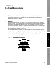
Installation Procedure Accuracy ConsiderationsElectrical ConnectionsIntroduction
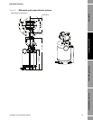
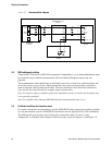
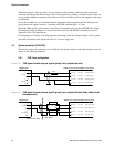
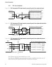
Figure 3-3 Schematic block diagram of meter circuit (2-wire system)
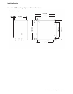
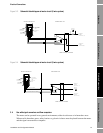
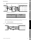
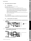
Figure 3-4 Schematic block diagram of meter circuit (3-wire system)
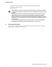
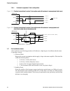
3.4 Use with signal converters and flow computers
The meter can be operated in two general environments, either in safe areas or in hazardous areas.
When used in hazardous areas, safety barriers or galvanic isolators must be placed between the meter
and the signal converter/flow computer.
A
D
B
C
CYLINDER
ACTIVATING
COIL
PICK OFF
COIL
PART OF
SPOOLBODY
VIBRATING
CYLINDER
PICK OFF CURRENT
CYLINDER DRIVE CURRENT
USER CONNECT BOARD
NEGATIVE
SUPPLY
VOLTAGE (0V)
SIGNAL
OUTPUT
330R
POSITIVE
SUPPLY
VOLTAGE (+V)
SENSING ELEMENT AMPLIFIER UNIT
A
D
B
C
CYLINDER
ACTIVATING
COIL
PICK OFF
COIL
PART OF
SPOOLBODY
VIBRATING
CYLINDER
PICK OFF CURRENT
CYLINDER DRIVE CURRENT
USER CONNECT BOARD
NEGATIVE
SUPPLY
VOLTAGE (0V)
SIGNAL
OUTPUT
POSITIVE
SUPPLY
VOLTAGE (+V)
SENSING ELEMENT AMPLIFIER UNIT