


– 3 –
4.3 Installation work
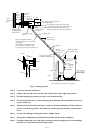
For installation of the analyzer locker and the extractor, follow the piping instructions in Fig. 4-1 and the
separately issued approval drawings (outline diagrams, sampling system diagram).
(1) Countermeasures for cold climate
(a) Freeze prevention of gas piping
(b) Freeze prevention of drain pot
(c) Freeze prevention of bypass and drain pipes
(2) Countermeasurement for vibration
When installing in a place where vibration is considerable, the locker should be floated on antivibration
rubber pads.
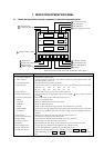
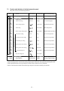
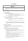
4.4 Connection of cables
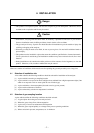
Caution
• Request an installation company or your dealer to carry out wiring.
If wiring is incomplete, shock hazard or injury may be caused.
• Class D grounding construction is mandatory. Otherwise, shock hazard may be caused.
<Caution for wiring company>
For preventing shock hazard, fire and injury, be sure to observe the following.
• Before wiring, be sure to turn off the primary power supply. If this is neglected, you may receive and
electric shock.
• For grounding, use a 600 V-IV wire having diameter of 2 mm
2
or more and an adequate dielectric
strength.
• Connect the power supply which meets the rating of product. Connection of other power supply may
cause a fire.
• Select the diameter of input and output wires, which matches the rated current of gas analyzer.
• Be sure to use solderless terminals for connection to the input and output terminal block.
• Use the terminal block for branching the output wire.
• Be sure to fix the input and output wires onto the floor, wall surface, etc. and use a protective device for
wires.
The lead-in for AC power cables and outlet for signal wires are provided at the bottom of the analyzer or else
at the specified place. Connect AC power cables and output signal wires according to the separately issued
wiring diagrams.
Note: Avoid connecting the analyzer power supply near devices such as high-frequency heating fur-
nace or electric welder which greatly disturb the power waveform, and avoid sharing the same
power lines with such devices. Class D grounding construction (100W ground resistance) is
required.
4.5 Connection of pipes (refer to piping instructions in Fig. 4-1 and separately issued approval
drawings)
(1) Connect gas pipe between the gas extractor and the analyzer inlet (sample gas inlet). Use a joint, etc.
for ø10/ø8 Teflon pipe when connecting to ensure there will be no leakage.
(2) Additionally tighten the joint section if necessary