


– 31 –
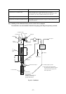
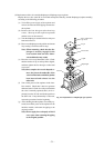
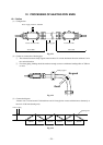
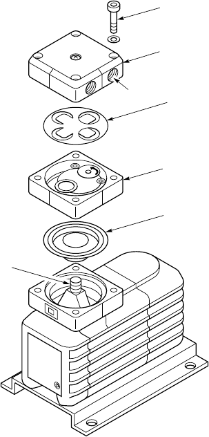
Hex. socket head
cap screw
Cap A
Seat valve
Rc1/8
Cap B
Diaphragm
Arm lot
Fig. 10-4 Exploded view of diaphragm type aspirator
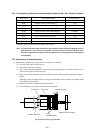
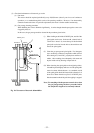
(4) Replacement of the valve and the diaphragm of diaphragm type aspirator
Replace the seat valve (turn 90° in six months and replace annually) and the diaphragm (replace annually)
according to the following procedure.
(a) Turn off the power supply of the aspirator and
remove the inlet and outlet piping connected to
the aspirator.
(b) Remove the four hexagon socket head cap
screws. Then cap A and cap B are separated
and the valve can be removed.
(c) Turn the diaphragm counterclockwise with your
hand and remove it.
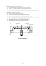
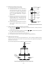
(d) Place a new diaphragm to the position and mount
it by turning it clockwise until it stops.
Note) When mounting, check that the dia-
phragm is securely engaged in the
screw section of the arm slot. Other-
wise malfunction may result.
(e) Place the valve on cap B and turn it 90∞. Check
that the notches of cap A and cap B are aligned,
and then tighten the four hexagon socket head
cap screws.
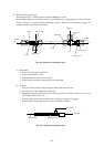
Note) Since complex valve seat is adopted, re-
move the pin on the underside of the
valve from the hole to which the pin has
been inserted and reinsert it to the
other hole.
(f) Turn on the power of the aspirator in the inter-
face module. Check that it does not generate
abnormal sound. Check also with your hand that
the valve is normally operated, that is, air is as-
pirated from the IN side and discharged from
the OUT side. If any abnormality is observed,
repeat the procedure from the beginning.
(g) After checking that the aspirator is normally op-
erated, turn off the power of the aspirator in the
interface module, and return the piping to the
original position.
Note) Do not apply force abruptly to Rc1/8
screw part when returning the piping
to the original position.