


– 33 –
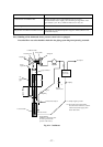
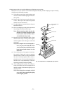
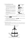
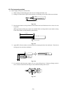
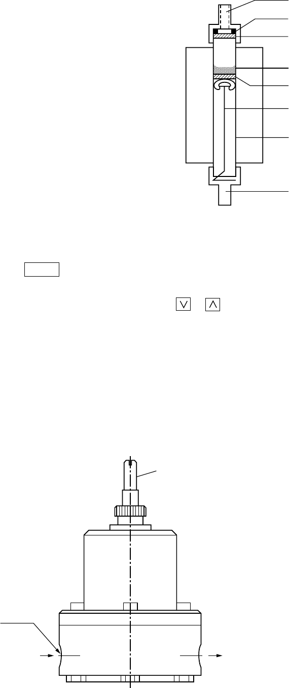
(6) Replacement of NO
2
/NO converter catalyst
(a) Turn off power supply to the converter.
(b) After half an hour, remove q w e, and extract r
upward and downward, respectively. Pay attention
not to suffer a burn. In addition, carefully handle the
ceramic pipe for preventing breakage. When remov-
ing r , e will fall simultaneously. So prepare a
catalyst receiver.
(c) Wind glass wool on the tip of r and insert it from
the bottom together with q. Inject one pack of new
catalyst from the top. Set w e on the top side. (This
step is unnecessary when a membrane filter is pro-
vided at the later stage.)
(d) Connect the pipe, set the temperature controller at
220°C (200°C for NO/CO analyzer), and turn on
power supply.
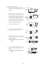
(7) Setting of temperature controller for NO
2
/NO converter (PXZ4)
(a) When pressing the PV/SV key, display changes over between PV and SV. (Usually, PV (Process
Variable) display is set).
(b) Under SV (Set Value) display, set 220°C by pressing the or key and determine it by the ENT
key. (200°C need be set for NO/CO analyzer.)
(c) Parameter need not be set because they have been factory-set.
(d) The temperature controller controls converter temperature through the SSR relay.
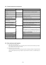
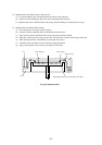
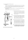
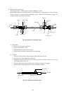
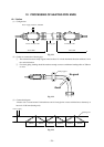
(8) Setting of pressure control valve
The pressure control valve has been set the discharge about 2 N/min. of sample gas together with drain,
when the pressure at the inlet is about 50 kPa. The set pressure increases with a right turn of the setting knob
and decreases with a left turn.
Do not turn the setting knob unless the sample flow needs to be changed.
Connection
rubber
Filter
Ring
Filter
Fastener
Ceramic
pipe
Connection
rubber
Catalyst
q
w
e
r
e
t
y
q
Fig. 10-6 Structure of NO
2
/NO converter
IN
OUT
Setting knob
2-Rc1/4
Sample
Fig. 10-7 External appearance of pressure control valve