


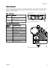
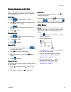

Run Screens
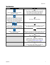
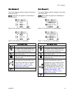
Run Screen 2
This screen displays pressure settings for the active
pump and profile.
NOTE: Some fie
lds are grayed out, depending on
setup select
ions.
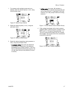
Figure 8 Run Screen 2, in Pressure Mode
Figure 9
Run Screen 2, in Flow Mode
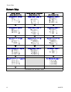
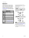
Run Screen 2 Key
Enter the screen.
For systems with multiple pumps and
one display, select the desired pump (1
to 8), using the pull-down menu.
Select the desired profile (1 to 4), using
the pull-down menu.
Select from the profile drop-down menu
to stop the pump.
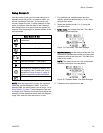
Displays pressure maximum (first data
field), target (second data field), and
minimum (third data field), as selected
in Setup Screen 2, page 18.See
Setup Screen 4, page 20 to set or
disable the pressure alarms.
Ex
it the screen.
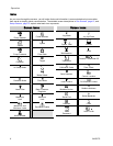
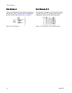
Run Screen 3
This screen displays fluid flow settings for the active
pump and profile.
NOTE: Some fie
lds are grayed out, depending on
setup select
ions.
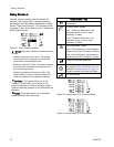
Figure10 RunScreen3,inPressureMode
Figure 1
1 Run Screen 3, in Flow Mode
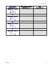
RunScreen3Key
Enter the screen.
For systems with multiple pumps and
one display, select the desired pump (1
to 8), using the pull-down menu.
Select the desired profile (1 to 4), using
the pull-down menu.
Select from the profile drop-down menu
to stop the pump.
The first line displays the maximum
flow rate and maximum cycle rate
(displayed as a cpm conversion of the
maximum flow setting). The second
line displays the target flow rate. The
third line displays the minimum flow
rate. See SetupScreen3,page19to
establish these settings. See
Setup Screen 4, page 20 to set or
disable the flow alarms.
E
xit the screen.
3A2527D 13