


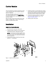
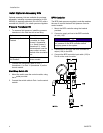

Installation
Cable Connect
ion
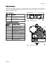
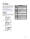
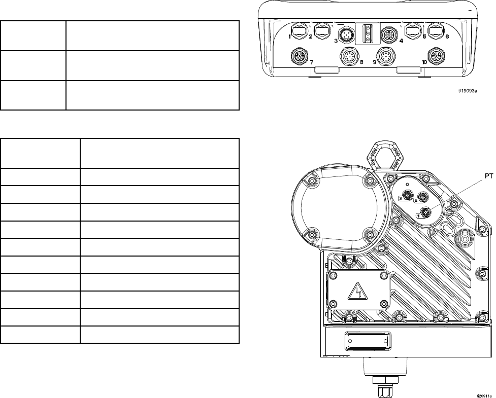
Order an accessory cable (C) from Table 1. Connect the cable to Port 3 on the bottom of the control module
(see Fig. 2). Connect the other end to the power terminal (PT) on the motor (see Fig. 3). Connect other
cables as described in Table 2.
Table 1 CAN Cables
Cable Part
No.
Description
16P911
Intrinsically safe CAN cable, female
x female, 3 ft (1 m)
16P912
Intrinsically safe CAN cable, female
x female, 25 ft (8 m)
Table 2 AD
CM Cable Connections
ADCM Port
Number
Connector Purpose
1
Fiber Op
tic RX - to PLC
2
Fiber Optic TX - to PLC
3
Power and CAN communication
4
Start
/stop input
5
Fiber Optic RX - to next ADCM
6
Fiber Optic TX - tos next ADCM
7
Pressure transducer 1
8 BPR
control 4-20mA output
9 Not used
10 Pressure transducer 2
Figure 2 ADCM Connectors
Figure 3 Motor Power Terminal
3A2527D 5