


Appendix B. Pump
Control from a P LC
Appendix B. Pu
mp Control from a PLC
This guide shows how to use the information in
Appendix A to control a pump remotely from a PLC.
The steps progress from basic pump control to more
advanced monitoring and alarm control features.
It is importa
nt that you first follow all directions in the
Setup Screen
s to configure your system properly.
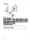
Test that th
e pump operates correctly when controlled
from the Dis
play. Make sure the display, fiber optics,
communicat
ion gateway, and PLC are connected
properly. R
efer to Communication KIt manual. Use
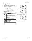
Setup Scre
en 12 to enable remote control and set
your modbu
s preferences.
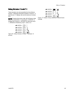
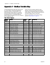
1. Enable PLC control: Set register 404200 to 1.
2. Run a pump: Set register 404201. Enter 0 for
stopped,1 to 4 for the desired profile.
3. View pump profile: Read register 404201. This
register updates automatically to reflect the
actual pump status. If the profile is changed from
the display, this register changes as well. If the
pump stops due to an alarm, this register will
read 0.
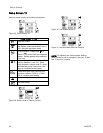
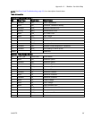
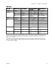
4. View pump status: Read register 404100 to see
the status of the pump. See Appendix A, Table
6, for a description of each bit.
• Example 1: Register 404100, bit 1, reads 1 if
the pump is currently moving.
• Example 2: Register 404100, bit 2 reads 1 if
the pump has an active alarm.
5. Monitor alarms and deviations: Read register
404112 to 404115. Each bit in these registers
corresponds to an alarm or deviation. See
Appendix A, Table 5. I
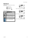
• Example 1: Pressure falls below the minimum
setting entered on Setup Screen 2. It will show
on bit 4 of register 404113 if minimum pressure
is set to Alarm, and on bit 5 of register 404113
if minimum pressure is set to Deviation.
•Example2:
The system is set up for a
pressure t
ransducer on Setup Screen 8, but no
transduce
r is detected. It will show on bit 1 of
register 4
04114.
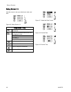
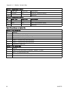
6. Monitor pump cycle rate, flow rate, and pressure:
Read registers 404101 to 404105. Note that
pressure is available only if a pressure transducer
is connected to the display. Register 404104
shows the pressure on transducer 1. Register
404105 shows the pressure on transducer 2. See
Appendix A, Table 7 for units for these registers.
• Example 1: If register 404101 reads 75, the
pump speed is 7.5 cycles/minute.
•Exampl
e 2: If register 404103 reads 67, the
pump is
operating at 67 percent pressure.
7. Reset active alarms and deviations: Clear the
condition that caused the alarm. Set register
404202, bit 0, to 1 to clear the alarm. The pump
will be in profile 0 due to the alarm. Set 404201
to the desired profile to run the pump again.
38 3A2527D