Control Module
Control Modul
e
The Control Module provides the interface for users
to enter selections and view information related to
setup and operation.
The screen backlight is factory set to remain on,
even without screen activity. See Setup Screen 4
to set the backlight timer to your preference. Press
any key to restore.
Keys are used to input numerical data, enter setup
screens, navigate within a screen, scroll through
screens, and select setup values.
Installation
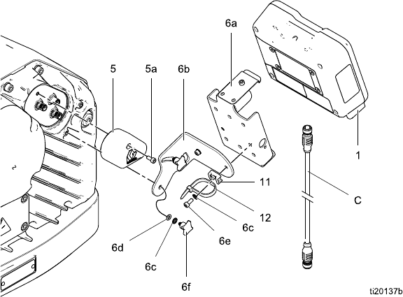
Install the Control Module
1. Shut off and lock out power to the motor.
2. Install the jumper connector (5) over the top two
terminals of the motor, using the screw (5a).
NOTE: To connect up to 8 motors together, see
Appendix A in the E-Flo DC Motor Manual, where
the control module is the referenced intrinsically
safe (IS) apparatus.
3. Assemble the bracket kit (6a-6f) and the holder
and tie (11, 12) as shown.
4. Install the module (1) in the bracket (6a), making
sure the tabs at the bottom of the bracket engage
the slots in the module, and the lip at the top of
the bracket holds the module securely in place.
5. Connect the accessory cable (C), using the
tie (12) as a strain relief as shown. See
Cable Connection, page 5 .
6. Restore power to the motor.
Figure 1 Install the Control Module
3A2527D 3


