


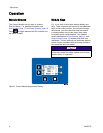
Operation
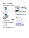
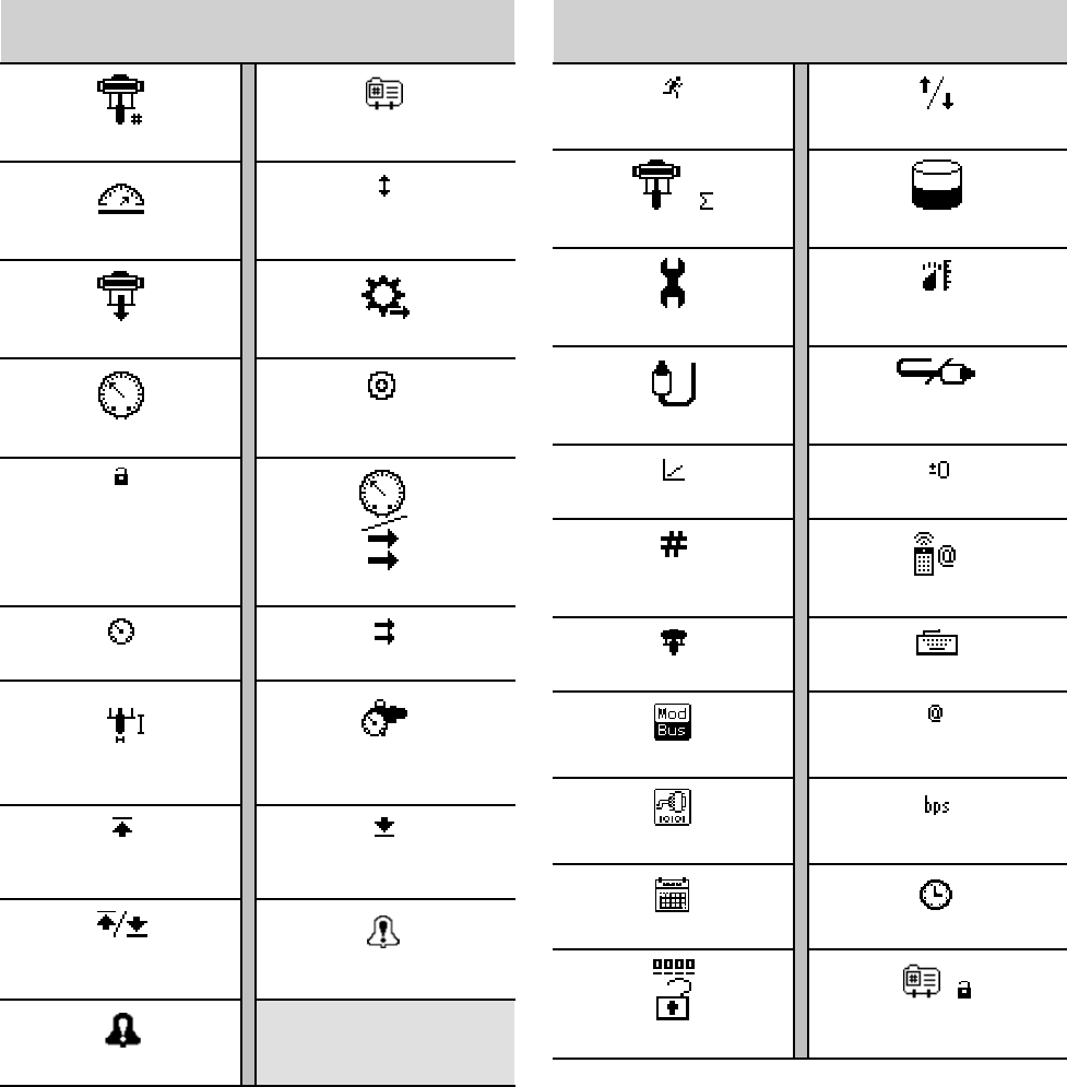
Icons
Asyoumovethr
ough the screens, you will notice that most information is communicated using icons rather
than words to s
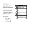
implify global communication. The detailed screen descriptions in RunScreens,page12, and
Setup Screens
,page16, explain what each icon represents.
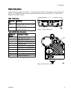
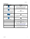
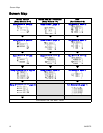
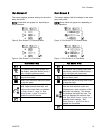
Screen Icons
Pump Number
Profile Number
Speed
Cycles
Pump Pressure Flow Rate
Pressure
Target
In Setup Mode
Mode Select
Pressure Mode Flow Mode
Lower Size Back Pressure
Regulator
Maximum
Limit
Minimum
Limit
Maximum and
Minimum Limits
Deviation Enable
Ala
rm Enable
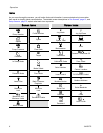
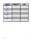
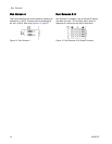
Screen Icons
Jog Mode
Jog Up/Down
Cycles Total Volume
Maintenance
Units
Transducer
Pressure Transducer Off
Calibration Scale Zero Offset
Serial Number
Control Location
Local C
ontrol
PLC/Re
mote Control
Modbus Device
Modbus Address
Serial Port
Serial Baudrate
Calendar Clock
Password
Lock Profile
8 3A2527D