


-28-
Model G0757Z (Mfd. Since 02/15)
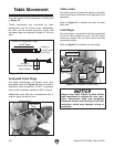
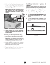
Table Movement
The table travels in three directions, as illustrated
in Figure 19.
These movements are controlled by table
handwheels and the Z-axis crank. Additionally,
the table can be moved along the X-axis with
the power feed and manually rotated 45° left and
right.
X-Axis or Longitudinal Travel
(Left & Right)
Y-Axis or
Cross Travel
(In & Out)
Z-Axis or
Vertical Elevation
(Up & Down)
Figure 19. The directions of table movement.
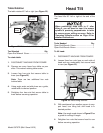
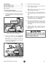
Graduated Index Rings
The table handwheels and Z-axis crank have
graduated rings (see Figure 20) that are used to
determine table movement in 0.001" increments
with one full revolution equaling 0.200" of travel.
Additionally, each dial has a thumbscrew that is
used to adjust the dial to zero.
Figure 20. Locations of graduated rings.
Graduated
Rings
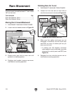
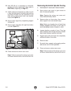
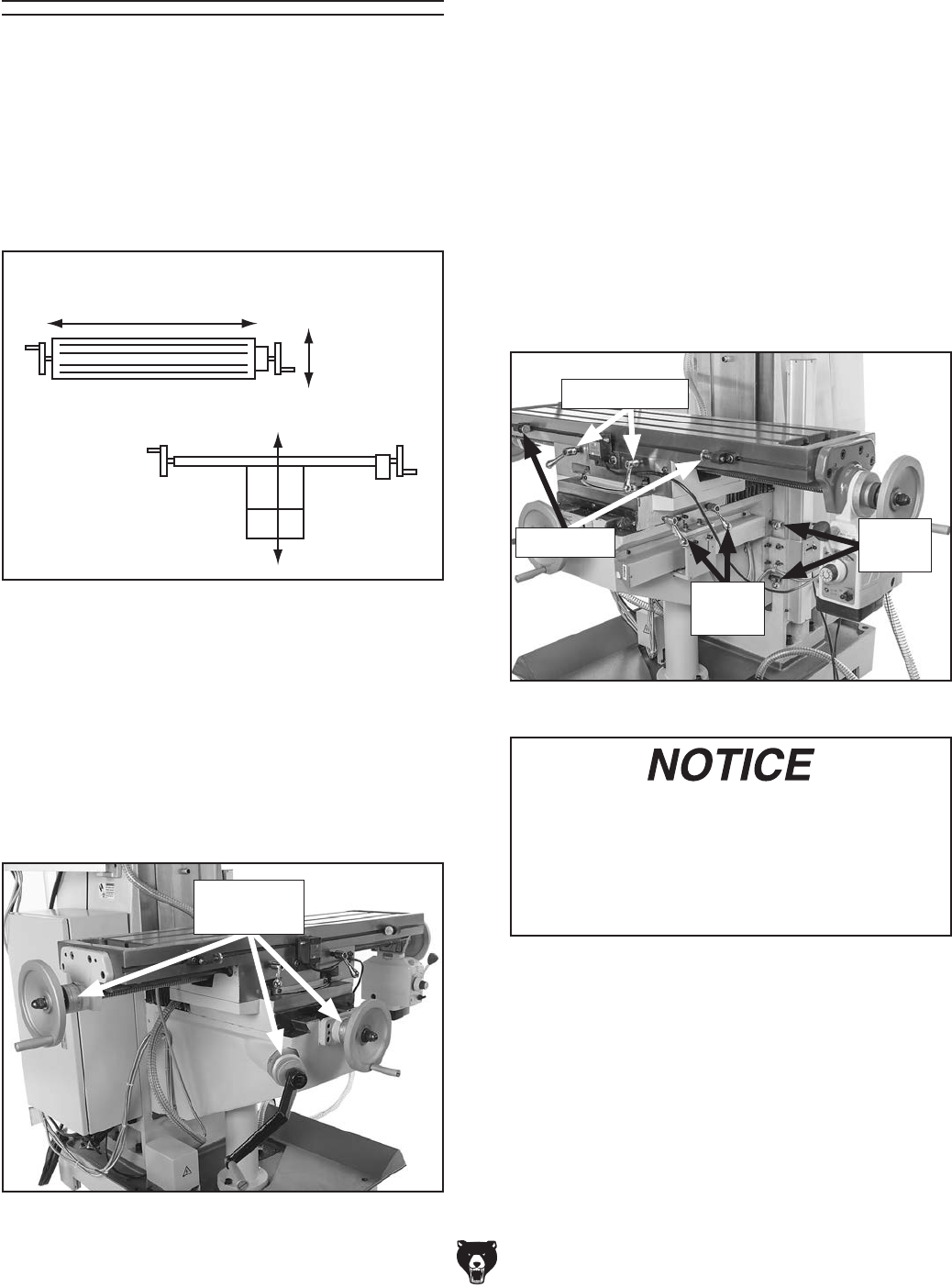
Table Locks
Use table locks to increase the rigidity of the table
when movement in that axis is not required for the
operation.
Refer to Figure 21 to identify the locks for each
table axis.
Limit Stops
Use limit stops in conjunction with the powerfeed
to set the total amount of travel. The limit stops
come into contact with the limit switch and stop
powerfeed motion.
Refer to Figure 21 to identify the limit stops.
Figure 21. Locations of table locks.
X-Axis Locks
Y-Axis
Locks
Z-Axis
Locks
Always keep table locked in place unless
table movement is required for your oper-
ation. Unexpected table and workpiece
movement could cause tooling to bind with
workpiece, which may damage tooling or
workpiece.
Limit Stop