


Model G0757Z (Mfd. Since 02/15)
-59-
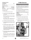
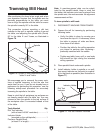
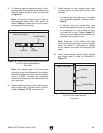
5. To measure spindle alignment along X-axis,
place parallel block directly under spindle and
indicator across length of table, as illustrated
in Figure 78.
Note: If you must re-position quill or knee to
accommodate above step, then review the
tasks in Step 2 to make sure the mill is prop-
erly prepared for tramming.
Parallel Block
Indicator
Spindle
Table (Top View)
Figure 78. Parallel block and indicator positioned
for the X-axis measurement
(top view).
Note: Your general goal in the next steps
should be to get the difference of the indicator
readings between the ends of the parallel bar
down to 0.0005". However, the acceptable
variance will depend on the requirements for
your operation.
6. Rotate spindle by hand so that indicator point
rests on one end of parallel block, as illus-
trated in Figures 77–78, then zero dial.
7. Rotate spindle so that indicator point rests
in same manner on other end of block, then
read dial.
— If indicator dial still reads zero or is within
the acceptable variance, continue on with
Step 8.
— If indicator dial has moved from zero
beyond acceptable variance, you will need
to compensate for that amount by rotat-
ing head left or right. Repeat Steps 6–7
until you are satisfied with the spindle axis
alignment along table X-axis.
Note: Keep one of the rotation lock bolts
just snug so the head does not move loosely
while you adjust it. Remember to tighten
all the rotation lock bolts after adjusting the
head.
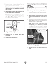
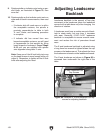
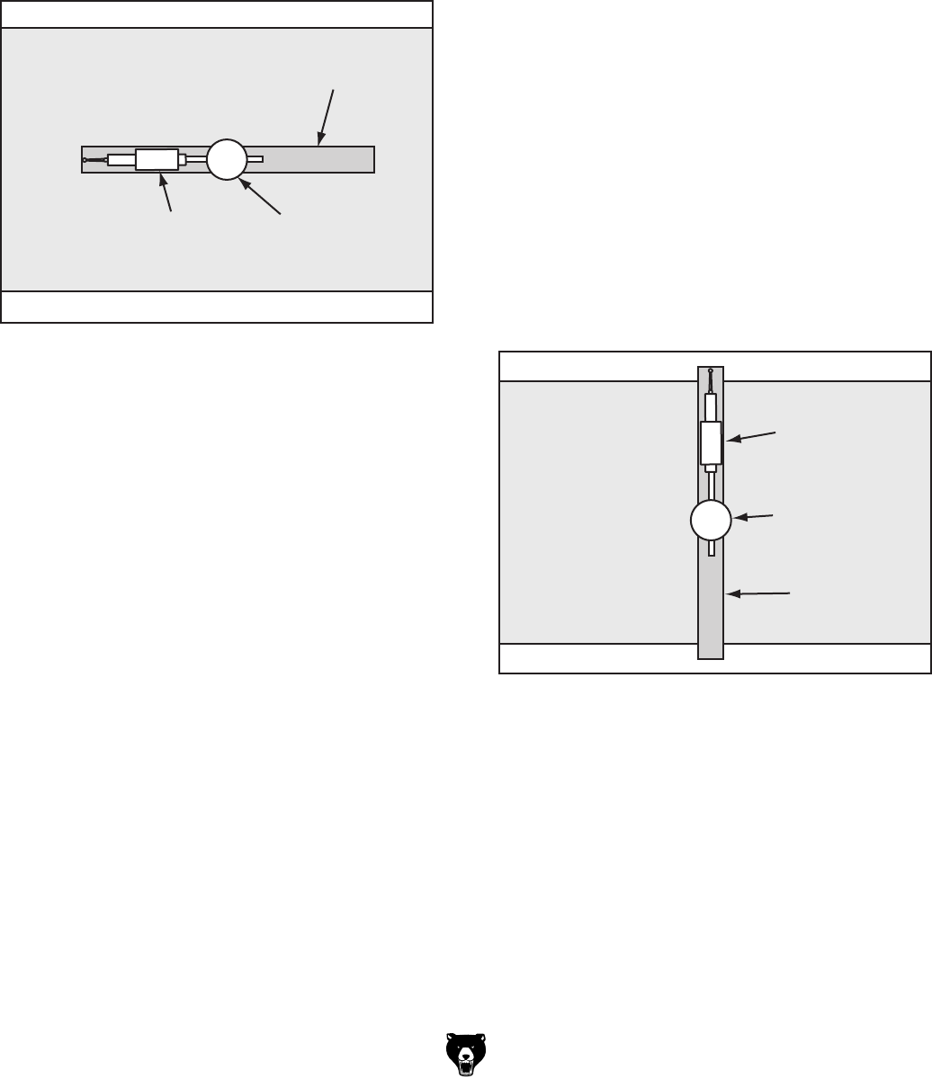
8. Place parallel block directly under spindle
and across width of table, as illustrated in
Figure 79.
Parallel Block
Indicator
Spindle
Table (Top View)
Figure 79. Parallel block and indicator positioned
for the Y-axis measurement
(top view).