


-60-
Model G0757Z (Mfd. Since 02/15)
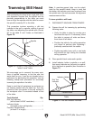
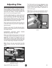
9. Rotate spindle so indicator point rests on par-
allel block, as illustrated in Figure 79, then
zero dial.
10. Rotate spindle so that indicator point rests on
other end of block in same manner, then read
dial.
— If indicator dial still reads zero or is within
the acceptable variance, the spindle is
precisely perpendicular to table in both
X- and Y-axes, and tramming procedure
is complete.
— If indicator dial has moved from zero
beyond acceptable variance, you will need
to compensate for that amount by tilting
head forward or backward. Repeat Steps
9–10 until you are satisfied with spindle
axis alignment along table Y-axis.
Note: Keep one of the tilt lock bolts just snug
so the head does not move loosely while you
adjust it. Remember to tighten all the tilt lock
bolts after adjusting the head.
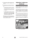
Adjusting Leadscrew
Backlash
Leadscrew backlash is the amount of free play
movement in the leadscrew (when the leadscrew
moves but the table does not) after changing the
direction of rotation.
A leadscrew must have a certain amount of back-
lash to rotate easily, but over time, it increases
with wear. Generally, 0.005"–0.010" leadscrew
backlash is acceptable to ensure smooth move-
ment and reduce the risk of premature thread
wear.
The X-axis leadscrew backlash is adjusted using
a long 4mm hex wrench to tighten/loosen the cap
screws on the leadscrew nut. This adjusts the force
the leadscrew nut exerts on the leadscrew threads.
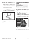
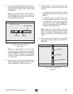
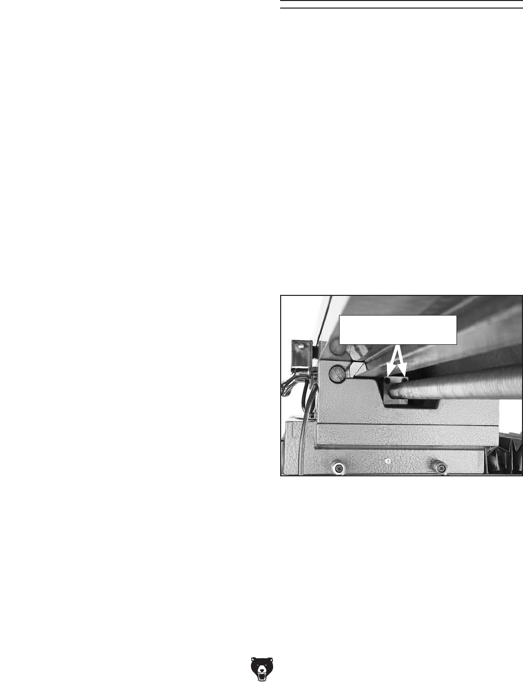
The X-axis leadscrew nut shown in Figure 80 is
accessed from underneath the right side of the
table.
Figure 80. Location of X-axis leadscrew nut cap
screws for adjusting backlash.
X-Axis Leadscrew Nut
Cap Screws