


-58-
Model G0757Z (Mfd. Since 02/15)
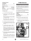
After positioning the head at an angle and when
your operation requires that the spindle axis be
precisely perpendicular to the table, you must
tram or align the spindle with the table to ensure
the spindle is exactly 90° to the table.
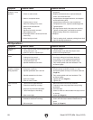
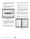
This procedure involves mounting a dial test
indicator to the quill or spindle, rotating it around
the table, and adjusting the spindle axis (Z-axis)
90° to the table X- and Y-axes, as illustrated in
Figure 76.
Table
Spindle
X-Axis
Y-Axis
Z-Axis
90º
90º
Figure 76. Spindle Z-axis perpendicular to the
table X- and Y-axis.
We encourage you to research the many varia-
tions of spindle tramming to find the one that
works best for you. If you do not already have a
preference for performing this operation, use the
following widely-used procedure for accurately
tramming the spindle to the table.
Keep in mind that all workpiece top surfaces are
not exactly parallel with the table top. You may
choose to tram the spindle to the top surface of
the workpiece after it is mounted instead of that
of the table.
Tools Needed Qty
Dial Test Indicator
(with at least 0.0005" resolution) ................ 1
Indicator Holder
(mounted on the quill/spindle) .................... 1
Precision Parallel Block
(at least 9" in length) ................................... 1
Note: A precision-ground plate can be substi-
tuted for the parallel blocks. Keep in mind that
the farther the indicator point can be placed from
the spindle axis, the more accurate the alignment
measurements will be.
To tram spindle to mill head:
1. DISCONNECT MACHINE FROM POWER!
2. Prepare the mill for tramming by performing
following tasks:
• Verify the table is clean by running your
hand over the top of it. If necessary, stone
the table to remove all nicks and burrs,
then clean off all debris.
• Position the table for the milling operation
you intend to perform after tramming—
preferably centered with the saddle.
• Tighten any table, knee, quill, or ram locks
that should be tight during the intended
milling operation.
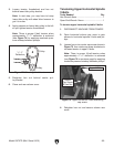
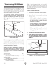
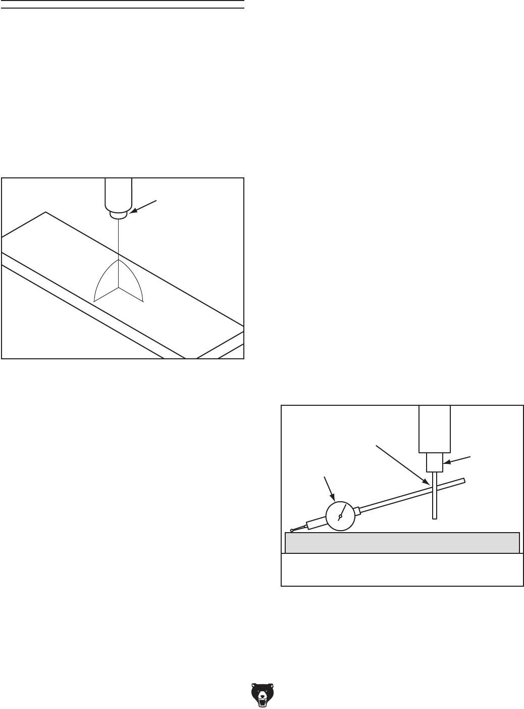
3. Place parallel block underneath spindle.
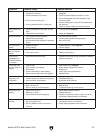
4. Install indicator holder in spindle or on quill,
then mount indicator so that point is as paral-
lel to the block as possible (see illustration in
Figure 77).
Tramming Mill Head
Table
Spindle
Dial Test
Indicator
Indicator Holder
Parallel Block
Figure 77. Dial test indicator mounted.