


Model G0757Z (Mfd. Since 02/15)
-37-
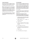
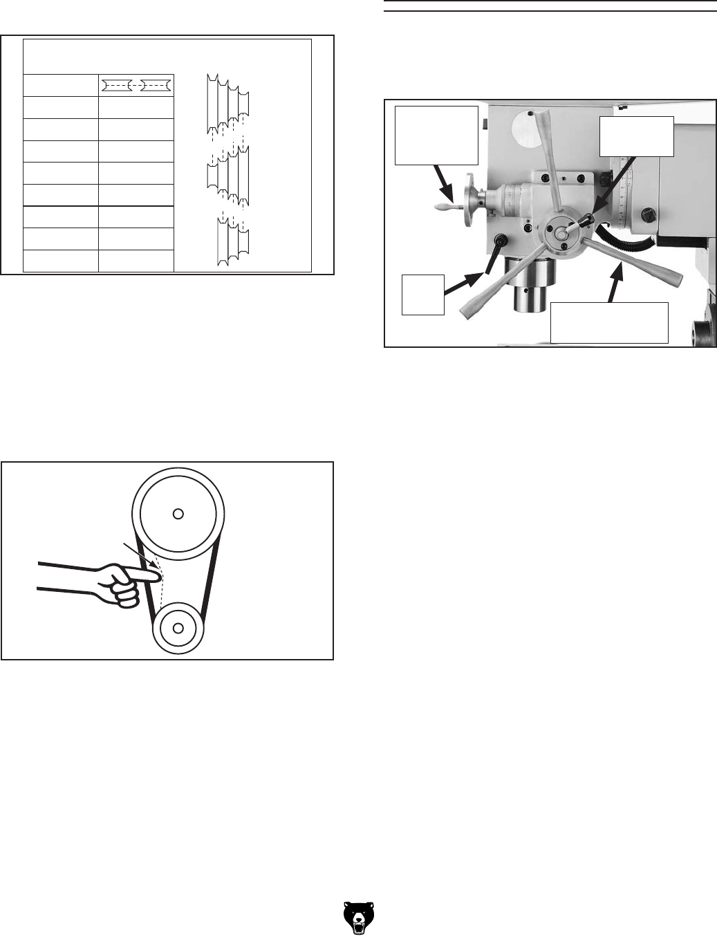
Using Spindle
Downfeed Controls
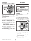
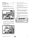
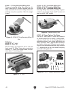
Use Figure 39 and the descriptions below to
understand the downfeed components that con-
trol the 5" spindle downfeed travel.
Figure 39. Spindle downfeed controls.
Fine
Downfeed
Handwheel
Coarse
Downfeed Lever
Selection
Lever
Quill
Lock
Coarse Downfeed Levers: Manually control
downfeed travel in a rapid manner. Generally
used for drilling operations. Spindle automatically
returns to top position when pressure is released
from the handle.
Fine Downfeed Handwheel: Manually controls
downfeed travel in a slow, precise manner. Unlike
coarse downfeed, spindle does not automatically
retract. The attached graduated dial has incre
-
ments of 0.001" with one full revolution represent-
ing 0.100" of travel. Generally used for milling
o
perations.
Selection Lever: When tightened, enables the
fine downfeed handwheel; conversely, when loos
-
ened enables the coarse downfeed levers.
Q
uill Lock: Secures the quill in place for increased
stability during milling operations.
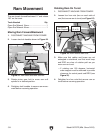
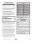
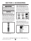
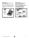
5. Arrange V-belts for desired horizontal spindle
speed (see Figure 37).
Note: Horizontal spindle speed chart shown
below is also on side of column.
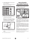
Vertical Spindle Speeds
285 860
1320
1720
2300
D – E D – G
A – F
A – G
B – G
C – E
D – F
B – E
C – F
390
490
585
665
RPM RPM
A
B
C
D
E
F
G
Spindle Motor
Upper
Motor
Horizontal Spindle Speeds
72 A – G
B – G
C – G
A – F
170
210
240
RPM
A – E290
B – F550
C – E830
B – D1300
A
E
F
G
B
C
D
Figure 37. Horizontal spindle speed chart.
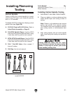
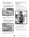
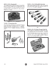
6. Apply pressure on lower idler pulley to left as
you tighten tension thumbwheel.
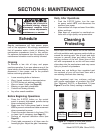
Note: There is proper V-belt tension when
approximately
1
⁄4" –
1
⁄2" deflection is achieved
by applying moderate pressure midway
between pulleys as shown in Figure 38.
7. Retighten hex nut behind lower idler pulley
bracket.
8. Close and latch V-belt cover.
Pulley
1
⁄
4
"–
1
⁄
2
"
Deflection
Pulley
Figure 38. Checking V-belt tension.