


HoneywellHoneywell
Honeywell Cabling and connections 29(96)
6
6.1.1 Cabling
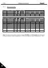
Use cables with heat resistance of at least +70
°
C. The cables and the fuses must be dimensioned
according to the tables below. Installation of cables according to UL regulations is presented in Chapter
6.1.4.
The fuses function also as cable overload protection.
These instructions apply only to cases with one motor and one cable connection from the frequency
converter to the motor. In any other case, ask the factory for more information.
1
st
environment
(restricted
distribution)
2
nd
environment
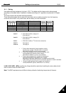
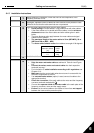
Cable type Level H/C Level L Level T Level N
Mains cable 1 1 1 1
Motor cable 3* 2 1 1
Control cable 4 4 4 4
Table 6-1. Cable types required to meet standards.
Level C =
EN 61800-3 (2004), category C1
EN 61000-6-3
Level H
= EN 61800-3 (2004), category C2
EN 61000-6-4
Level L
= EN61800-3 (2004), 2
nd
environment (industrial)
Level T:
See page 9.
Level N:
See page 9.
1 = Power cable intended for fixed installation and the
specific mains voltage. Shielded cable not required.
(NKCABLES/MCMK or similar recommended)
2 = Power cable equipped with concentric protection wire
and intended for the specific mains voltage.
(NKCABLES /MCMK or similar recommended).
3 = Power cable equipped with compact low-impedance
shield and intended for the specific mains voltage.
(NKCABLES /MCCMK, SAB/ÖZCUY-J or similar recommended).
*360º earthing of both motor and FC connection required to meet the standard
4 = Screened cable equipped with compact low-impedance
shield (NKCABLES /jamak, SAB/ÖZCuY-O or similar).
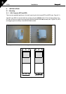
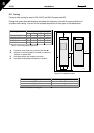
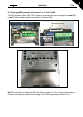
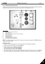
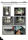
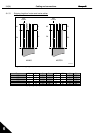
In NXL HVAC (MF4 – MF6): A cable entry flange should be used when installing the motor cable at both
ends in order to reach the EMC levels.
Note: The EMC requirements are fulfilled at factory defaults of switching frequencies (all frames).