


Control Keypad 79(96)
7
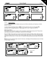
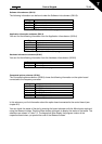
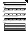
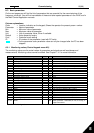
Status Word
15 14 13 12 11 10 9 8 7 6 5 4 3 2 1 0
- - - - - - - - F Z AREF W FLT DIR RUN RDY
Information about the status of the device and messages is indicated in the Status word. The Status
word is composed of 16 bits the meanings of which are described in the table below:
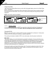
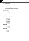
Actual speed
15 14 13 12 11 10 9 8 7 6 5 4 3 2 1 0
MSB LSB
This is actual speed of the frequency converter. The scaling is –10000...10000. In the application,
the value is scaled in percentage of the frequency area between set minimum and maximum
frequency.
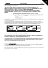
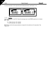
Control word
15 14 13 12 11 10 9 8 7 6 5 4 3 2 1 0
- - - - - - - - - - - - - RST DIR RUN
In Honeywell applications, the three first bits of the control word are used to control the frequency
converter. However, you can customise the content of the control word for your own applications
because the control word is sent to the frequency converter as such.
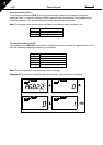
Speed reference
15 14 13 12 11 10 9 8 7 6 5 4 3 2 1 0
MSB LSB
This is the Reference 1 to the frequency converter. Used normally as Speed reference. The allowed
scaling is –10000...10000. In the application, the value is scaled in percentage of the frequency area
between the set minimum and maximum frequencies.
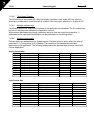
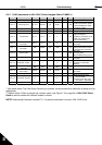
Bit definitions
Description Bit
Value = 0 Value = 1
RUN Stop Run
DIR Clockwise Counter clockwise
RST Rising edge of this bit will reset active fault
RDY Drive not ready Drive ready
FLT No fault Fault active
W No warning Warning active
AREF Ramping Speed reference reached
Z - Drive is running at zero speed
F - Flux Ready