


NXL HVAC Basic speed control – Quick setup 95(96)
12
12. NXL HVAC BASIC SPEED CONTROL – QUICK SETUP
This chapter provides basic setup instructions for the user of NXL HVAC inverters, when using Basic
Speed Control in HVAC applications.
What you need to know
Motor nameplate data
Nominal current
Nominal speed
Speed signal specification
Signal type (V, mA)
Range (0-10, 2-10, 0-20, 4-20)
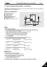
Setup
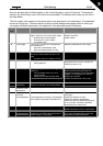
1 Run the Start-up Wizard
Note: Running the Start Up Wizard resets all parameters to their default values.
•
Hold STOP button down for 5 seconds
•
Select application type FAN or PUMP and confirm with ENTER
•
Select motor nominal speed and confirm with ENTER
•
Select motor nominal current and confirm with ENTER
•
For speed signal 0 – 10 V use AI1 (Analogue Input 1)
•
All settings DONE
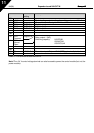
2 Control Signal Settings for Speed Signals other than 0 – 10 V
•
For other selections full parameter view is needed:
P2.1.14 Parameter Conceal Set to 0 (not in use)
•
For speed signal 2 – 10 V use Analogue Input 1
P2.2.6 AI1 Signal Range Set to 4 (2 – 10 V)
•
For speed signal 4 – 20 mA use Analogue Input 2
P2.1.15.14 I/O Reference Set to 1 (AI2)
•
For speed signal 0 – 20 mA use Analogue Input 2
P2.1.15.14 I/O Reference Set to 1 (AI2)
P2.2.12 AI2 Signal Range Set to 1 (0 – 20 mA)
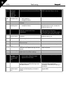
Manual Test
1 Hold LEFT down for 3-5 seconds
Control Place automatically switches to Keypad
2 Use normal keypad buttons for speed control
•
UP and DOWN to adjust the speed
•
START and STOP for control
3 Hold LEFT down for 3 seconds to return to remote control (I/O or Fieldbus)
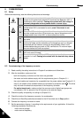
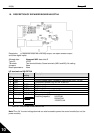
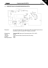
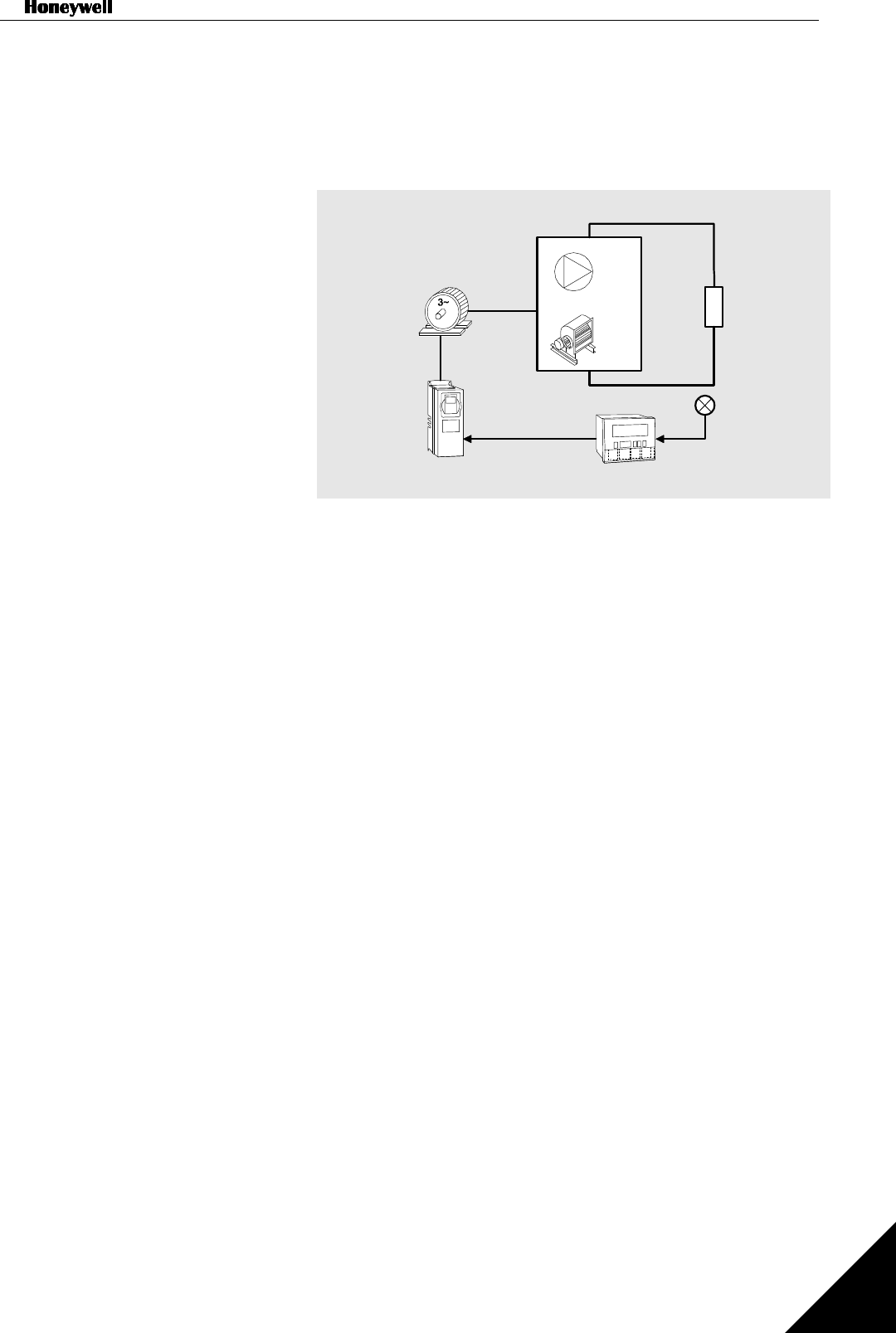
Pump
Fan
or
Load
Pressure
Sensor
Control System
Variable Frequency Drive
Motor
Speed Signal
V signal to AI1
mA signal to AI2